
Quick Reference Guide
Page 16
... Several devices are the files and settings?, click to protect against power fluctuations and failures: • Surge protectors • Line conditioners • Uninterruptible power supplies (UPS) 16 Quick Reference Guide TRANSFER DATA TO THE DESTINATION COMPUTER 1 Go to the destination computer. 2 Under Now go to your settings and files, then ...
... Several devices are the files and settings?, click to protect against power fluctuations and failures: • Surge protectors • Line conditioners • Uninterruptible power supplies (UPS) 16 Quick Reference Guide TRANSFER DATA TO THE DESTINATION COMPUTER 1 Go to the destination computer. 2 Under Now go to your settings and files, then ...

Quick Reference Guide
Page 17
...printer, to maintain AC voltage at a fairly constant level. Line conditioners are designed to a separate power strip that provides surge protection. The battery charges while AC power is approved by nearby lightning strikes. A device with surge protection help prevent damage to your computer ...that provides temporary power to connected devices when AC power is being saved to the hard drive may result in your area, disconnect the telephone line from the telephone wall jack and disconnect your computer from the electrical outlet. Uninterruptible Power Supplies NOTICE: Loss ...
...printer, to maintain AC voltage at a fairly constant level. Line conditioners are designed to a separate power strip that provides surge protection. The battery charges while AC power is approved by nearby lightning strikes. A device with surge protection help prevent damage to your computer ...that provides temporary power to connected devices when AC power is being saved to the hard drive may result in your area, disconnect the telephone line from the telephone wall jack and disconnect your computer from the electrical outlet. Uninterruptible Power Supplies NOTICE: Loss ...
Quick Reference Guide
Page 58
..., 21 line-out, 21 Starting the Dell Diagnostics from the Drivers and Utilities disc, 37 Starting the Dell Diagnostics From Your Hard Drive, 36 support website, 7 T transferring information to a new computer, 13 troubleshooting beep codes, 33 conflicts, 35 Dell Diagnostics, 36 diagnostic lights, 29 Hardware Troubleshooter, 35 power lights, 27 system messages, 34 U uninterruptible power supply.
..., 21 line-out, 21 Starting the Dell Diagnostics from the Drivers and Utilities disc, 37 Starting the Dell Diagnostics From Your Hard Drive, 36 support website, 7 T transferring information to a new computer, 13 troubleshooting beep codes, 33 conflicts, 35 Dell Diagnostics, 36 diagnostic lights, 29 Hardware Troubleshooter, 35 power lights, 27 system messages, 34 U uninterruptible power supply.

User's Guide
Page 4
Dell OpenManage Client Instrumentation . . . . . 47 Power Management 47 About RAID Configurations 49 RAID Level 0 50 RAID Level 1 51 RAID Level 5 51 Configuring Your Computer for RAID 53 Configuring Your ...Internet Connection 68 Transferring Information to a New Computer 69 Microsoft® Windows® XP 70 Microsoft Windows Vista 73 Power Protection Devices 73 Surge Protectors 74 Line Conditioners 74 Uninterruptible Power Supplies 74 5 Securing Your Computer 75 Chassis Intrusion Detection 75 Removing the Chassis Intrusion Switch 75 Replacing the Chassis Intrusion Switch...
Dell OpenManage Client Instrumentation . . . . . 47 Power Management 47 About RAID Configurations 49 RAID Level 0 50 RAID Level 1 51 RAID Level 5 51 Configuring Your Computer for RAID 53 Configuring Your ...Internet Connection 68 Transferring Information to a New Computer 69 Microsoft® Windows® XP 70 Microsoft Windows Vista 73 Power Protection Devices 73 Surge Protectors 74 Line Conditioners 74 Uninterruptible Power Supplies 74 5 Securing Your Computer 75 Chassis Intrusion Detection 75 Removing the Chassis Intrusion Switch 75 Replacing the Chassis Intrusion Switch...
User's Guide
Page 8
... 160 Replacing the Computer Cover 161 I/O Panel 163 I/O-Panel Components 164 Removing the I/O Panel 165 Replacing the I/O Panel 167 Power Supply 167 Power Supply DC Connector Pin Assignments . . 167 Removing the Power Supply 174 Replacing the Power Supply 176 Battery 176 About the Battery 176 Replacing the Battery 177 Processor 179 Removing the Processor 179 Installing the Processor...
... 160 Replacing the Computer Cover 161 I/O Panel 163 I/O-Panel Components 164 Removing the I/O Panel 165 Replacing the I/O Panel 167 Power Supply 167 Power Supply DC Connector Pin Assignments . . 167 Removing the Power Supply 174 Replacing the Power Supply 176 Battery 176 About the Battery 176 Replacing the Battery 177 Processor 179 Removing the Processor 179 Installing the Processor...
User's Guide
Page 27
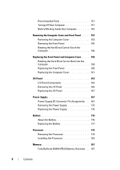
Hard Drive Bay Rotated Out 1 2 3 5 4 1 power supply 4 front fan 2 system board 5 card fan 3 memory fan About Your Computer 27 1 power supply 3 FlexBay 5 upper 5.25-inch drive bay 2 rotatable hard drive bay 4 lower 5.25-inch drive bay Inside View -
Hard Drive Bay Rotated Out 1 2 3 5 4 1 power supply 4 front fan 2 system board 5 card fan 3 memory fan About Your Computer 27 1 power supply 3 FlexBay 5 upper 5.25-inch drive bay 2 rotatable hard drive bay 4 lower 5.25-inch drive bay Inside View -
User's Guide
Page 41
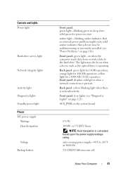
... on the system board 875 W 1094W or 3732BTU/hour NOTE: Heat dissipation is present. yellow light for 10-Mb operation; auto-sensing power supply-90 V to the hard drive. Back panel: green light for a 1000-Mb (1-Gb) operation Front panel: displays solid green when ...50/60 Hz 3-V CR2032 lithium coin cell About Your Computer 41 Controls and Lights Power light Hard-drive access light Network integrity lights Activity light Diagnostic lights Standby power light Power DC power supply Wattage Heat dissipation Voltage Backup battery Front panel: green light-blinking green in sleep ...
... on the system board 875 W 1094W or 3732BTU/hour NOTE: Heat dissipation is present. yellow light for 10-Mb operation; auto-sensing power supply-90 V to the hard drive. Back panel: green light for a 1000-Mb (1-Gb) operation Front panel: displays solid green when ...50/60 Hz 3-V CR2032 lithium coin cell About Your Computer 41 Controls and Lights Power light Hard-drive access light Network integrity lights Activity light Diagnostic lights Standby power light Power DC power supply Wattage Heat dissipation Voltage Backup battery Front panel: green light-blinking green in sleep ...
User's Guide
Page 46
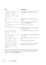
Boot: Failure to Boot to verify system presence. Power Supply: Critical Power Supply Problem The computer power supply voltage is out of limits. Password: System Password The system password is disabled. Voltage: Generic Critical The voltage from integrated ...BIOS The BIOS did not complete loading upon initiation. For more information about Dell's ASF implementation, see the ASF User's Guide and the ASF Administrator's Guide, which are available on the Dell Support website at support.dell.com. 46 Advanced Features Alert Description Chassis: Chassis Intrusion - Physical Security ...
Boot: Failure to Boot to verify system presence. Power Supply: Critical Power Supply Problem The computer power supply voltage is out of limits. Password: System Password The system password is disabled. Voltage: Generic Critical The voltage from integrated ...BIOS The BIOS did not complete loading upon initiation. For more information about Dell's ASF implementation, see the ASF User's Guide and the ASF Administrator's Guide, which are available on the Dell Support website at support.dell.com. 46 Advanced Features Alert Description Chassis: Chassis Intrusion - Physical Security ...

User's Guide
Page 73
...The wizard reads the collected files and settings and applies them to protect against power fluctuations and failures: • Surge protectors • Line conditioners • Uninterruptible power supplies (UPS) Setting Up Your Computer 73 Follow the instructions on the screen by... the Windows Easy Transfer wizard. NOTE: For more information about this procedure, search support.dell.com for transferring your new computer. Power Protection Devices Several devices...
...The wizard reads the collected files and settings and applies them to protect against power fluctuations and failures: • Surge protectors • Line conditioners • Uninterruptible power supplies (UPS) Setting Up Your Computer 73 Follow the instructions on the screen by... the Windows Easy Transfer wizard. NOTE: For more information about this procedure, search support.dell.com for transferring your new computer. Power Protection Devices Several devices...

User's Guide
Page 74
... help prevent damage to your computer from the telephone wall jack and disconnect your computer to connected devices when AC power is approved by nearby lightning strikes. Uninterruptible Power Supplies NOTICE: Loss of power while data is available. UPS devices contain a battery that can occur during electrical storms. Line Conditioners NOTICE: Line conditioners do...
... help prevent damage to your computer from the telephone wall jack and disconnect your computer to connected devices when AC power is approved by nearby lightning strikes. Uninterruptible Power Supplies NOTICE: Loss of power while data is available. UPS devices contain a battery that can occur during electrical storms. Line Conditioners NOTICE: Line conditioners do...

User's Guide
Page 123
... Pattern Problem Description A possible processor failure has occurred. A possible system board failure has occurred. Contact Dell for technical assistance (see "Contacting Dell" on page 295). Contact Dell for technical assistance (see "Contacting Dell" on exists. Verify that both power supply cables are not properly connected. A possible system board failure has occurred. Troubleshooting Tools 123 Suggested Resolution...
... Pattern Problem Description A possible processor failure has occurred. A possible system board failure has occurred. Contact Dell for technical assistance (see "Contacting Dell" on page 295). Contact Dell for technical assistance (see "Contacting Dell" on exists. Verify that both power supply cables are not properly connected. A possible system board failure has occurred. Troubleshooting Tools 123 Suggested Resolution...
User's Guide
Page 156
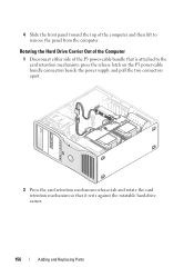
4 Slide the front panel toward the top of the P3 power-cable bundle that it rests against the rotatable hard-drive carrier. 156 Adding and Replacing Parts Rotating the Hard Drive Carrier Out of the Computer 1 Disconnect either side of the computer and then lift to the card retention mechanism: press the release latch on the P3 power-cable bundle connectors beside the power supply and pull the two connectors apart. 2 Press the card retention mechanism release-tab and rotate the card retention mechanism so that is attached to remove the panel from the computer.
4 Slide the front panel toward the top of the P3 power-cable bundle that it rests against the rotatable hard-drive carrier. 156 Adding and Replacing Parts Rotating the Hard Drive Carrier Out of the Computer 1 Disconnect either side of the computer and then lift to the card retention mechanism: press the release latch on the P3 power-cable bundle connectors beside the power supply and pull the two connectors apart. 2 Press the card retention mechanism release-tab and rotate the card retention mechanism so that is attached to remove the panel from the computer.

User's Guide
Page 167
Replacing the I/O Panel NOTICE: Ensure that you replace all cables originally attached to the I/O panel or you may experience computer problems. 1 Follow "Removing the I/O Panel" on page 165 in reverse order. Power Supply Power Supply DC Connector Pin Assignments Adding and Replacing Parts 167
Replacing the I/O Panel NOTICE: Ensure that you replace all cables originally attached to the I/O panel or you may experience computer problems. 1 Follow "Removing the I/O Panel" on page 165 in reverse order. Power Supply Power Supply DC Connector Pin Assignments Adding and Replacing Parts 167

User's Guide
Page 168
1 1 power supply screws (4) DC Power Connectors P1 13 14 15 16 17 18 19 20 21 22 23 24 1 2 3 4 5 6 7 8 9 10 11 12 168 Adding and Replacing Parts
1 1 power supply screws (4) DC Power Connectors P1 13 14 15 16 17 18 19 20 21 22 23 24 1 2 3 4 5 6 7 8 9 10 11 12 168 Adding and Replacing Parts

User's Guide
Page 174
... follow the safety instructions in "Before You Begin" on page 153. 3 Disconnect the cables from the power supply. 4 Remove the four screws that attach the power supply to components inside your computer, discharge static electricity from the electrical outlet before you touch any of the... procedures in the Product Information Guide. See "Removing the Computer Cover" on page 151. 2 Remove the computer cover. Removing the Power Supply CAUTION: Before performing any of your body before opening the cover. CAUTION: To guard against electrical shock, always unplug your computer from...
... follow the safety instructions in "Before You Begin" on page 153. 3 Disconnect the cables from the power supply. 4 Remove the four screws that attach the power supply to components inside your computer, discharge static electricity from the electrical outlet before you touch any of the... procedures in the Product Information Guide. See "Removing the Computer Cover" on page 151. 2 Remove the computer cover. Removing the Power Supply CAUTION: Before performing any of your body before opening the cover. CAUTION: To guard against electrical shock, always unplug your computer from...

User's Guide
Page 175
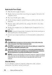
1 2 1 power supply screws (4) 2 power cable harness connector 5 Slide the power supply toward the front of the computer by approximately one inch. 6 Lift the power supply out of the computer. Adding and Replacing Parts 175
1 2 1 power supply screws (4) 2 power cable harness connector 5 Slide the power supply toward the front of the computer by approximately one inch. 6 Lift the power supply out of the computer. Adding and Replacing Parts 175
User's Guide
Page 176
...on. The battery can explode if it into place. 2 Replace the four screws that secure the power supply to the back of the computer chassis. 3 Reconnect the DC power cables. 4 On the desktop computer, reattach the power cables to the side of the hard drive. 5 Run the cables underneath the tabs, and press..., follow the safety instructions in the Product Information Guide. CAUTION: A new battery can last several years. 176 Adding and Replacing Parts Replacing the Power Supply 1 Slide the power supply into the computer. 7 Connect your computer and devices to the manufacturer's instructions.
...on. The battery can explode if it into place. 2 Replace the four screws that secure the power supply to the back of the computer chassis. 3 Reconnect the DC power cables. 4 On the desktop computer, reattach the power cables to the side of the hard drive. 5 Run the cables underneath the tabs, and press..., follow the safety instructions in the Product Information Guide. CAUTION: A new battery can last several years. 176 Adding and Replacing Parts Replacing the Power Supply 1 Slide the power supply into the computer. 7 Connect your computer and devices to the manufacturer's instructions.

User's Guide
Page 209
... drive. General Drive Installation Guidelines NOTICE: If metal shields are keyed for correct insertion; When you install a drive, you connect two cables-a DC power cable from the power supply and a data cable-to the back of the data cable will connect to either an expansion card or to the system board. Most connectors...
... drive. General Drive Installation Guidelines NOTICE: If metal shields are keyed for correct insertion; When you install a drive, you connect two cables-a DC power cable from the power supply and a data cable-to the back of the data cable will connect to either an expansion card or to the system board. Most connectors...
User's Guide
Page 220
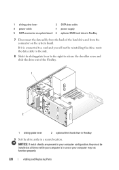
... the FlexBay. 1 2 1 sliding-plate lever 2 optional third hard drive in FlexBay 9 Set the drive aside in a secure location. 1 sliding-plate lever 2 SATA data cable 3 power cable 4 power supply 5 SATA connector on the system board. If it is connected to a card and you will not be installed at all times while your computer is...
... the FlexBay. 1 2 1 sliding-plate lever 2 optional third hard drive in FlexBay 9 Set the drive aside in a secure location. 1 sliding-plate lever 2 SATA data cable 3 power cable 4 power supply 5 SATA connector on the system board. If it is connected to a card and you will not be installed at all times while your computer is...
User's Guide
Page 224
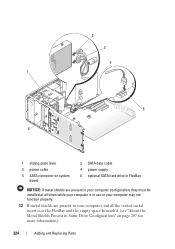
2 3 4 1 5 6 1 sliding-plate lever 3 power cable 5 SATA connector on system board 2 SATA data cable 4 power supply 6 optional SATA hard drive in FlexBay NOTICE: If metal shields are present in your computer configuration, they must be installed at all times while your computer is in use or your computer may not function properly. 12 If metal shields are present in your computer, install the vented metal insert over the FlexBay and the empty space beneath it (see "About the Metal Shields Present in Some Drive Configurations" on page 207 for more information): 224 Adding and Replacing Parts
2 3 4 1 5 6 1 sliding-plate lever 3 power cable 5 SATA connector on system board 2 SATA data cable 4 power supply 6 optional SATA hard drive in FlexBay NOTICE: If metal shields are present in your computer configuration, they must be installed at all times while your computer is in use or your computer may not function properly. 12 If metal shields are present in your computer, install the vented metal insert over the FlexBay and the empty space beneath it (see "About the Metal Shields Present in Some Drive Configurations" on page 207 for more information): 224 Adding and Replacing Parts


