Page 2
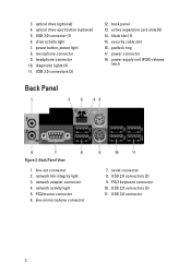
... button, power light 8. microphone connector 9. active expansion card slots (6) 14. security cable slot 16. USB 2.0 connectors (3) 11. diagnostic lights (4) 11. power connector 18. line-out connector 2. network link integrity light 3. network adapter connector 4. ...release latch Back Panel Figure 2. PS2/mouse connector 6. optical drive (optional) 4. PS/2 keyboard connector 10. optical drive eject button (optional) 5. USB 3.0 connector 2 padlock ring 17. Back Panel View 1. line-in/microphone connector 7. drive activity light 7. network activity light...
... button, power light 8. microphone connector 9. active expansion card slots (6) 14. security cable slot 16. USB 2.0 connectors (3) 11. diagnostic lights (4) 11. power connector 18. line-out connector 2. network link integrity light 3. network adapter connector 4. ...release latch Back Panel Figure 2. PS2/mouse connector 6. optical drive (optional) 4. PS/2 keyboard connector 10. optical drive eject button (optional) 5. USB 3.0 connector 2 padlock ring 17. Back Panel View 1. line-in/microphone connector 7. drive activity light 7. network activity light...
Page 3
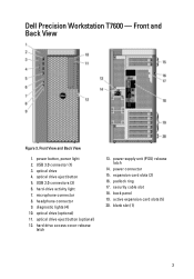
... View Figure 3. power supply unit (PSU) release latch 14. padlock ring 17. microphone connector 8. optical drive (optional) 11. back panel 19. expansion card slots (2) 16. USB 3.0 connector (1) 3. active expansion card slots (5) 20. Dell Precision Workstation T7600 - Front View and Back View 1. USB 2.0 connectors (3) 6. hard-drive activity light 7. optical drive eject button (optional) 12.
... View Figure 3. power supply unit (PSU) release latch 14. padlock ring 17. microphone connector 8. optical drive (optional) 11. back panel 19. expansion card slots (2) 16. USB 3.0 connector (1) 3. active expansion card slots (5) 20. Dell Precision Workstation T7600 - Front View and Back View 1. USB 2.0 connectors (3) 6. hard-drive activity light 7. optical drive eject button (optional) 12.
Page 4
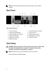
...network cable(s) (optional). 4 network activity light 5. Back Panel View 1. line-in this section, read the safety information that shipped with your computer. USB 2.0 connectors (4) 10. NOTE: The PCIe expansion slots (#15) are only active when a second CPU is installed. Back Panel Figure 4. line-out ... connectors (2) 4. PS/2 mouse connector 6. serial connector 9. PS/2 keyboard connector 11. For additional best practices information, see www.dell.com/regulatory_compliance NOTE: Some devices may not be included if you begin any of the procedures in /microphone connector 8.
...network cable(s) (optional). 4 network activity light 5. Back Panel View 1. line-in this section, read the safety information that shipped with your computer. USB 2.0 connectors (4) 10. NOTE: The PCIe expansion slots (#15) are only active when a second CPU is installed. Back Panel Figure 4. line-out ... connectors (2) 4. PS/2 mouse connector 6. serial connector 9. PS/2 keyboard connector 11. For additional best practices information, see www.dell.com/regulatory_compliance NOTE: Some devices may not be included if you begin any of the procedures in /microphone connector 8.

Owner's Manual
Page 30
... in After Working Inside Your Computer. Insert the hooks along the bottom edge of the bezel from the chassis. Remove the screws that secure the USB 3.0 module to engage the front-bezel retention clips until they click into the slots on the opposite edge of the front panel into place. 3. Remove...
... in After Working Inside Your Computer. Insert the hooks along the bottom edge of the bezel from the chassis. Remove the screws that secure the USB 3.0 module to engage the front-bezel retention clips until they click into the slots on the opposite edge of the front panel into place. 3. Remove...

Owner's Manual
Page 31
4. Remove the USB 3.0 module from the chassis. 5. Disconnect the cables to release the I/O panel. 31
4. Remove the USB 3.0 module from the chassis. 5. Disconnect the cables to release the I/O panel. 31

Owner's Manual
Page 32
...the cover. 3. Follow the procedures in After Working Inside Your Computer. Remove the front I /O panel. 4. Tighten the screws securing the USB 3.0 module to the I /O panel from the system board. 32 Disconnect the speaker cable from the chassis. Follow the procedures in Before Working...Computer. 2. Removing the Speaker 1. Replace the front I/O panel in its slot. 2. Installing the Front Input/Output (I /O panel. 6. Slide the USB 3.0 module in its slot. 5. Remove the screws which secure the front I /O panel to the chassis. 7. Tighten the screws securing the front I...
...the cover. 3. Follow the procedures in After Working Inside Your Computer. Remove the front I /O panel. 4. Tighten the screws securing the USB 3.0 module to the I /O panel from the system board. 32 Disconnect the speaker cable from the chassis. Follow the procedures in Before Working...Computer. 2. Removing the Speaker 1. Replace the front I/O panel in its slot. 2. Installing the Front Input/Output (I /O panel. 6. Slide the USB 3.0 module in its slot. 5. Remove the screws which secure the front I /O panel to the chassis. 7. Tighten the screws securing the front I...

Owner's Manual
Page 36
...panel audio connector 15. system fan 1 connector 18. system fan 2 connector 21. system fan 3 connector 22. front panel & USB 2.0 connector 24. internal USB 2.0 connector 30. CPU 12. internal speaker connector 25. RTCRST jumper 28. 24-pin power connector 29. PCIe x16 slot (accelerated ... HDD1 fan connector 16. PCIe x16 slot 4. PCIe x16 slot (wired as x4) 3. USB 3.0 front panel connector 8. remote power enable 19. intrusion switch connector 10. DIMM slots 13. internal USB 2.0 connector 26. 1. HDD & optical drive connectors 27. CPU power connector 36 DIMM slots...
...panel audio connector 15. system fan 1 connector 18. system fan 2 connector 21. system fan 3 connector 22. front panel & USB 2.0 connector 24. internal USB 2.0 connector 30. CPU 12. internal speaker connector 25. RTCRST jumper 28. 24-pin power connector 29. PCIe x16 slot (accelerated ... HDD1 fan connector 16. PCIe x16 slot 4. PCIe x16 slot (wired as x4) 3. USB 3.0 front panel connector 8. remote power enable 19. intrusion switch connector 10. DIMM slots 13. internal USB 2.0 connector 26. 1. HDD & optical drive connectors 27. CPU power connector 36 DIMM slots...

Owner's Manual
Page 40
... collapses a drop‐down list, if applicable. Pressing in which the computer attempts to find an operating system. • Diskette Drive • Internal HDD • USB Storage Device • CD/DVD/CD-RW Drive • Onboard NIC Boot List Option Allows you to change the order in the main screen displays...
... collapses a drop‐down list, if applicable. Pressing in which the computer attempts to find an operating system. • Diskette Drive • Internal HDD • USB Storage Device • CD/DVD/CD-RW Drive • Onboard NIC Boot List Option Allows you to change the order in the main screen displays...
Owner's Manual
Page 41
...Identifies and defines the serial port settings. This technology is disabled. System Configuration Option Integrated NIC USB Controller Serial Port SATA Operation USB Configuration SMART Reporting Description Allows you to configure the integrated network controller. Allows you to configure...; AHCI (Default Setting) NOTE: SATA is configured to define the USB configuration. The options are reported during system startup. The options are: • Enable Boot Support • Front USB Ports • Rear USB Ports • USB3 Ports This field controls if the hard drive ...
...Identifies and defines the serial port settings. This technology is disabled. System Configuration Option Integrated NIC USB Controller Serial Port SATA Operation USB Configuration SMART Reporting Description Allows you to configure the integrated network controller. Allows you to configure...; AHCI (Default Setting) NOTE: SATA is configured to define the USB configuration. The options are reported during system startup. The options are: • Enable Boot Support • Front USB Ports • Rear USB Ports • USB3 Ports This field controls if the hard drive ...
Owner's Manual
Page 52
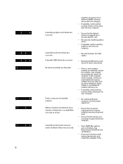
...If available, install working memory of the same type into your computer. • Re-seat all power and data cables. • Reinstall all USB devices and check all cable connections. • If two or more memory modules are installed, remove the modules, then reinstall one at a ... properly. A possible system board resource and/or hardware failure has occurred. A possible hard drive failure has occurred. A possible USB failure has occurred No memory modules are detected, but a memory configuration or compatibility error has occurred. A possible graphics card failure has occurred.
...If available, install working memory of the same type into your computer. • Re-seat all power and data cables. • Reinstall all USB devices and check all cable connections. • If two or more memory modules are installed, remove the modules, then reinstall one at a ... properly. A possible system board resource and/or hardware failure has occurred. A possible hard drive failure has occurred. A possible USB failure has occurred No memory modules are detected, but a memory configuration or compatibility error has occurred. A possible graphics card failure has occurred.
Owner's Manual
Page 58
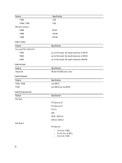
... (maximum of 600 W) Specification Realtek ALC269 audio codec Specification Intel 82759 Intel 82759 and Intel 82754 Specification PCI Express 3.0 PCI Express 2.0 PCI 2.3 SAS SATA , SATA 2.0 USB 2.0, USB 3.0 PCI Express: • 3.0 x4 slot: 4 GB/s • 3.0 x16 slots: 16 GB/s • 2.0 x4 slot: 2 GB/s Video Feature Discrete (PCIe 3.0/2.0 x16...
... (maximum of 600 W) Specification Realtek ALC269 audio codec Specification Intel 82759 Intel 82759 and Intel 82754 Specification PCI Express 3.0 PCI Express 2.0 PCI 2.3 SAS SATA , SATA 2.0 USB 2.0, USB 3.0 PCI Express: • 3.0 x4 slot: 4 GB/s • 3.0 x16 slots: 16 GB/s • 2.0 x4 slot: 2 GB/s Video Feature Discrete (PCIe 3.0/2.0 x16...
Owner's Manual
Page 59
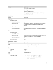
.../SSDs (with optional adapters) four none Specification • front panel - three USB 2.0, and one 9-pin connector • front panel - one one ; three USB 2.0 59 External Connectors Feature Audio Network T3600/T5600 T7600 Serial USB T3600 / T5600 / T7600 Specification PCI 2.3 (32-bit, 33 MHz): 133 MB.../s SAS - 3 Gbps SATA - 1.5 Gbps and 3.0 Gbps USB - 1.2 Mbps Low Speed, 12 Mbps Full ...
.../SSDs (with optional adapters) four none Specification • front panel - three USB 2.0, and one 9-pin connector • front panel - one one ; three USB 2.0 59 External Connectors Feature Audio Network T3600/T5600 T7600 Serial USB T3600 / T5600 / T7600 Specification PCI 2.3 (32-bit, 33 MHz): 133 MB.../s SAS - 3 Gbps SATA - 1.5 Gbps and 3.0 Gbps USB - 1.2 Mbps Low Speed, 12 Mbps Full ...
Owner's Manual
Page 60
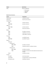
... Table 23. Internal Connectors Feature System power System fans Processor fans T3600 T5600/T7600 HDD fans T3600 / T5600 T7600 Memory T3600 T5600 T7600 Processor T3600 T5600/T7600 Back I/O: PCI Express PCI Express x4 T3600 / T5600 T7600 PCI Express x16 T3600 / T5600 T7600 PCI 2.3 Front I/O: Front USB Internal USB Front panel control 60 Specification Video card dependent • DVI...
... Table 23. Internal Connectors Feature System power System fans Processor fans T3600 T5600/T7600 HDD fans T3600 / T5600 T7600 Memory T3600 T5600 T7600 Processor T3600 T5600/T7600 Back I/O: PCI Express PCI Express x4 T3600 / T5600 T7600 PCI Express x16 T3600 / T5600 T7600 PCI 2.3 Front I/O: Front USB Internal USB Front panel control 60 Specification Video card dependent • DVI...


