Page 2
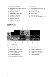
... cable slot 16. network activity light 5. USB 2.0 connectors (3) 11. microphone connector 9. Back Panel View 1. network adapter connector 4. PS2/mouse connector 6. USB 2.0 connectors (2) 9. optical drive eject button (optional) 5. back panel 13. padlock ring 17. USB 3.0 connector 2 3. USB 3.0 connector (1) 6. headphone connector 10. active expansion card slots (6) 14. power connector 18. power supply unit (PSU) release latch Back Panel Figure 2. network link integrity light 3. line-in/microphone connector 7. serial connector 8. PS/2 keyboard connector...
... cable slot 16. network activity light 5. USB 2.0 connectors (3) 11. microphone connector 9. Back Panel View 1. network adapter connector 4. PS2/mouse connector 6. USB 2.0 connectors (2) 9. optical drive eject button (optional) 5. back panel 13. padlock ring 17. USB 3.0 connector 2 3. USB 3.0 connector (1) 6. headphone connector 10. active expansion card slots (6) 14. power connector 18. power supply unit (PSU) release latch Back Panel Figure 2. network link integrity light 3. line-in/microphone connector 7. serial connector 8. PS/2 keyboard connector...
Page 3
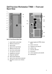
... expansion card slots (5) 20. Dell Precision Workstation T7600 - USB 3.0 connector (1) 3. diagnostic lights (4) 10. padlock ring 17. back panel 19. hard-drive activity light 7. optical drive eject button (optional) 12. blank slot (1) 3 power button, power light 2. USB 2.0 connectors (3) 6. optical drive (optional) 11. hard drive access cover-release latch 13. optical drive eject button 5. headphone connector 9. security cable slot 18. optical drive 4. power supply unit (PSU) release latch 14. Front and Back View Figure 3. Front View and Back View 1. power connector...
... expansion card slots (5) 20. Dell Precision Workstation T7600 - USB 3.0 connector (1) 3. diagnostic lights (4) 10. padlock ring 17. back panel 19. hard-drive activity light 7. optical drive eject button (optional) 12. blank slot (1) 3 power button, power light 2. USB 2.0 connectors (3) 6. optical drive (optional) 11. hard drive access cover-release latch 13. optical drive eject button 5. headphone connector 9. security cable slot 18. optical drive 4. power supply unit (PSU) release latch 14. Front and Back View Figure 3. Front View and Back View 1. power connector...
Page 4
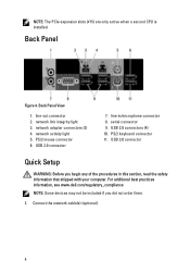
... of the procedures in /microphone connector 8. network adapter connectors (2) 4. Back Panel Figure 4. Back Panel View 1. line-in this section, read the safety information that shipped with your computer. USB 3.0 connector Quick Setup WARNING: Before you did not order them. 1. NOTE: The PCIe expansion slots (#15) are only active when a second CPU is installed. USB 2.0 connectors (4) 10. PS/2 keyboard connector 11. line-out connector 2. USB 2.0 connector 7. Connect the network cable(s) (optional). 4 network link integrity light 3. network activity light 5.
... of the procedures in /microphone connector 8. network adapter connectors (2) 4. Back Panel Figure 4. Back Panel View 1. line-in this section, read the safety information that shipped with your computer. USB 3.0 connector Quick Setup WARNING: Before you did not order them. 1. NOTE: The PCIe expansion slots (#15) are only active when a second CPU is installed. USB 2.0 connectors (4) 10. PS/2 keyboard connector 11. line-out connector 2. USB 2.0 connector 7. Connect the network cable(s) (optional). 4 network link integrity light 3. network activity light 5.
Owner's Manual
Page 5
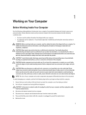
... any connector pins. if you are disconnecting this type of your computer and certain components may only be replaced or--if purchased separately--installed by the online or telephone service and support team. Also, before you begin working inside the computer. 1. Turn off your computer and all network cables from the computer. 4. Disconnect your computer (see the Regulatory Compliance Homepage at www.dell...
... any connector pins. if you are disconnecting this type of your computer and certain components may only be replaced or--if purchased separately--installed by the online or telephone service and support team. Also, before you begin working inside the computer. 1. Turn off your computer and all network cables from the computer. 4. Disconnect your computer (see the Regulatory Compliance Homepage at www.dell...
Owner's Manual
Page 6
... by running the Dell Diagnostics. 6 In Windows XP: Click Start → Turn Off Computer → Turn Off . After Working Inside Your Computer After you complete any replacement procedure, ensure you connect any telephone or network cables to their electrical outlets. 4. Shut down your operating system, press and hold the power button for about 6 seconds to dissipate static electricity, which could harm internal components. Replace the cover. In Windows Vista: Click Start , then...
... by running the Dell Diagnostics. 6 In Windows XP: Click Start → Turn Off Computer → Turn Off . After Working Inside Your Computer After you complete any replacement procedure, ensure you connect any telephone or network cables to their electrical outlets. 4. Shut down your operating system, press and hold the power button for about 6 seconds to dissipate static electricity, which could harm internal components. Replace the cover. In Windows Vista: Click Start , then...
Owner's Manual
Page 12
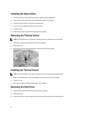
... may not ship with it from the hard drive. 12 Removing the Hard Drive 1. Remove the hard-drive power supply cable and the hard-drive data cable from the computer. Remove the cover. 3. Replace the thermal sensor in After Working Inside Your Computer. Follow the procedures in its slot and tighten the latch securing it . 1. Installing the Optical Drive 1. Follow the procedures in Before Working On Your Computer. 2. Installing the Thermal Sensor NOTE: The Thermal...
... may not ship with it from the hard drive. 12 Removing the Hard Drive 1. Remove the hard-drive power supply cable and the hard-drive data cable from the computer. Remove the cover. 3. Replace the thermal sensor in After Working Inside Your Computer. Follow the procedures in its slot and tighten the latch securing it . 1. Installing the Optical Drive 1. Follow the procedures in Before Working On Your Computer. 2. Installing the Thermal Sensor NOTE: The Thermal...
Owner's Manual
Page 14
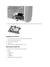
... from the latch. 14 Removing the System Fan 1. Unthread the system board cable from the hard-drive caddy. Connect the hard drive power supply cable. 3. Remove: a) cover b) intrusion switch c) PCI card d) hard drive e) optical drive 3. Follow the procedures in Before Working Inside Your Computer. 2. Connect the hard drive data cable. 4. 6. Follow the procedures in After Working Inside Your Computer. If a 2.5-inch hard drive is installed, remove the screws and lift up the drive to remove it inside the compartment. 2. Installing the Hard Drive 1. Install the cover. 5.
... from the latch. 14 Removing the System Fan 1. Unthread the system board cable from the hard-drive caddy. Connect the hard drive power supply cable. 3. Remove: a) cover b) intrusion switch c) PCI card d) hard drive e) optical drive 3. Follow the procedures in Before Working Inside Your Computer. 2. Connect the hard drive data cable. 4. 6. Follow the procedures in After Working Inside Your Computer. If a 2.5-inch hard drive is installed, remove the screws and lift up the drive to remove it inside the compartment. 2. Installing the Hard Drive 1. Install the cover. 5.

Owner's Manual
Page 35
... (I/O) panel g) PCI card h) PSU card i) system fan j) hard drive k) thermal sensor l) coin-cell battery m) optical drive n) cover o) PSU 5. Follow the procedures in the chassis. 2. Align the system board to the chassis. 3. Tighten the screws that secure the system board to the port connectors on the rear of the chassis and place the system board in After Working Inside Your Computer. Connect the cables to the system board. 4. System Board Components The following image displays the...
... (I/O) panel g) PCI card h) PSU card i) system fan j) hard drive k) thermal sensor l) coin-cell battery m) optical drive n) cover o) PSU 5. Follow the procedures in the chassis. 2. Align the system board to the chassis. 3. Tighten the screws that secure the system board to the port connectors on the rear of the chassis and place the system board in After Working Inside Your Computer. Connect the cables to the system board. 4. System Board Components The following image displays the...
Owner's Manual
Page 39
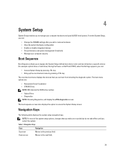
... hardware configuration • Enable or disable integrated devices • Set performance and power management thresholds • Manage your computer hardware and specify BIOS‐level options. The boot sequence screen also displays the option to access the System Setup screen. Table 1. During the Power-on Self Test (POST), when the Dell logo appears, you can : • Change the NVRAM settings after you make are : • Removable Drive (if available) • STXXXX Drive NOTE: XXX denotes the SATA drive number. • Optical Drive • Diagnostics...
... hardware configuration • Enable or disable integrated devices • Set performance and power management thresholds • Manage your computer hardware and specify BIOS‐level options. The boot sequence screen also displays the option to access the System Setup screen. Table 1. During the Power-on Self Test (POST), when the Dell logo appears, you can : • Change the NVRAM settings after you make are : • Removable Drive (if available) • STXXXX Drive NOTE: XXX denotes the SATA drive number. • Optical Drive • Diagnostics...
Owner's Manual
Page 41
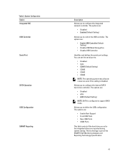
... You can set the serial port to configure the internal SATA hard-drive controller. Allows you to support RAID mode. The options are: • Enable Boot Support • Front USB Ports • Rear USB Ports • USB3 Ports This field controls if the hard drive errors for the integrated drives are : • Disabled • ATA • AHCI (Default Setting) NOTE: SATA is configured to configure the integrated network controller. This technology is disabled. The options are reported during system startup. Allows you to define the USB configuration. The options are...
... You can set the serial port to configure the internal SATA hard-drive controller. Allows you to support RAID mode. The options are: • Enable Boot Support • Front USB Ports • Rear USB Ports • USB3 Ports This field controls if the hard drive errors for the integrated drives are : • Disabled • ATA • AHCI (Default Setting) NOTE: SATA is configured to configure the integrated network controller. This technology is disabled. The options are reported during system startup. Allows you to define the USB configuration. The options are...
Owner's Manual
Page 44
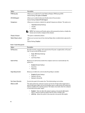
... enable the Execute Disable mode of the system fan. Allows the system to power on by special LAN signals when it receives a wake-up signal from entering Setup when an administrator password is unaffected by a special LAN signal. Default Setting: The option is applied after a AC power loss. Default Setting: Enable CPU XD Support Allows you to power up from the off state when triggered by this setting and must turn on automatically. Wake...
... enable the Execute Disable mode of the system fan. Allows the system to power on by special LAN signals when it receives a wake-up signal from entering Setup when an administrator password is unaffected by a special LAN signal. Default Setting: The option is applied after a AC power loss. Default Setting: Enable CPU XD Support Allows you to power up from the off state when triggered by this setting and must turn on automatically. Wake...
Owner's Manual
Page 45
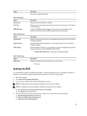
... available on replacing the system board or if an update is enabled by default. Restart the computer. 2. a) Enter the Service Tag or Express Service Code and click Submit. Allows you have your computer. This option is available. System Logs Option BIOS events Description Displays the system event log and allows you do not have your computer. b) Click Submit and proceed to support.dell.com/support/downloads. 3. Maintenance Option Service Tag...
... available on replacing the system board or if an update is enabled by default. Restart the computer. 2. a) Enter the Service Tag or Express Service Code and click Submit. Allows you have your computer. This option is available. System Logs Option BIOS events Description Displays the system event log and allows you do not have your computer. b) Click Submit and proceed to support.dell.com/support/downloads. 3. Maintenance Option Service Tag...

Owner's Manual
Page 46
... install the updated BIOS settings on your download method below window; NOTE: If the password jumper is disabled, the existing System Password and Setup Password is Unlocked. A password can assign a new System Password and/or Setup Password or change the System Password. Select Setup Password, type your computer. Click Run to save the file on your system password and press or . System and Setup Password You can create a system password and a setup password to log on the screen. Password Type Description System password Password...
... install the updated BIOS settings on your download method below window; NOTE: If the password jumper is disabled, the existing System Password and Setup Password is Unlocked. A password can assign a new System Password and/or Setup Password or change the System Password. Select Setup Password, type your computer. Click Run to save the file on your system password and press or . System and Setup Password You can create a system password and a setup password to log on the screen. Password Type Description System password Password...
Owner's Manual
Page 51
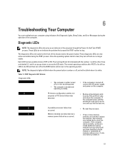
... , connect the AC power-supply and power-on the front of the computer. PCI device configuration activity is turned off or is not receiving power • The computer is booted and operating normally. • If the computer is in progress or PCI device failure was detected. • Remove all peripheral cards from the PCI and PCI-E slots and reboot the computer. 6 Troubleshooting Your Computer You can troubleshoot your computer using indicators like Diagnostic Lights, Beep Codes, and Error...
... , connect the AC power-supply and power-on the front of the computer. PCI device configuration activity is turned off or is not receiving power • The computer is booted and operating normally. • If the computer is in progress or PCI device failure was detected. • Remove all peripheral cards from the PCI and PCI-E slots and reboot the computer. 6 Troubleshooting Your Computer You can troubleshoot your computer using indicators like Diagnostic Lights, Beep Codes, and Error...
Owner's Manual
Page 52
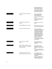
... board resource and/or hardware failure has occurred. If the computer starts normally, continue to a different DIMM connector and re-start the computer. • If available, install verified working graphics card into your computer. • Clear CMOS (Re-seat the coin-cell battery. A possible graphics card failure has occurred. A possible hard drive failure has occurred. See Removing and Installing Coincell Battery). • Disconnect all cable connections. • If two or more memory modules are using is supported...
... board resource and/or hardware failure has occurred. If the computer starts normally, continue to a different DIMM connector and re-start the computer. • If available, install verified working graphics card into your computer. • Clear CMOS (Re-seat the coin-cell battery. A possible graphics card failure has occurred. A possible hard drive failure has occurred. See Removing and Installing Coincell Battery). • Disconnect all cable connections. • If two or more memory modules are using is supported...
Owner's Manual
Page 53
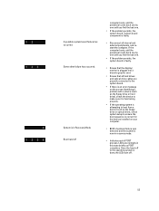
... Recovery Mode Boot hand off . 53 LEDs are properly connected to the system board. • If there is an error message on your computer. • BIOS checksum failure was detected and the system is faulty. • Disconnect all hard drives and optical-drive cables are normally in this state briefly as the floppy drive or optical drive), check system setup to the operating system is done, the LEDs turn off computer boots, add...
... Recovery Mode Boot hand off . 53 LEDs are properly connected to the system board. • If there is an error message on your computer. • BIOS checksum failure was detected and the system is faulty. • Disconnect all hard drives and optical-drive cables are normally in this state briefly as the floppy drive or optical drive), check system setup to the operating system is done, the LEDs turn off computer boots, add...
Owner's Manual
Page 60
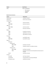
...System power System fans Processor fans T3600 T5600/T7600 HDD fans T3600 / T5600 T7600 Memory T3600 T5600 T7600 Processor T3600 T5600/T7600 Back I/O: PCI Express PCI Express x4 T3600 / T5600 T7600 PCI Express x16 T3600 / T5600 T7600 PCI 2.3 Front I/O: Front USB Internal USB Front panel control 60 Specification Video card dependent • DVI connector • DisplayPort • DMS-59 Specification one 28-pin connector three four-pin connectors one 5-pin connector two 5-pin connectors one 5-pin connector three 5-pin connectors four 240-pin connectors eight 240-pin connectors sixteen 240-pin...
...System power System fans Processor fans T3600 T5600/T7600 HDD fans T3600 / T5600 T7600 Memory T3600 T5600 T7600 Processor T3600 T5600/T7600 Back I/O: PCI Express PCI Express x4 T3600 / T5600 T7600 PCI Express x16 T3600 / T5600 T7600 PCI 2.3 Front I/O: Front USB Internal USB Front panel control 60 Specification Video card dependent • DVI connector • DisplayPort • DMS-59 Specification one 28-pin connector three four-pin connectors one 5-pin connector two 5-pin connectors one 5-pin connector three 5-pin connectors four 240-pin connectors eight 240-pin connectors sixteen 240-pin...
Owner's Manual
Page 61
...computer. blinking amber light - A good connection at 100 Mbs exists between the network and the computer. amber/blinking light - see the service manual for specific diagnostic codes. Controls and Lights Feature Power button light: Drive activity light Network link integrity lights (back panel) Network activity lights (back panel) Diagnostic lights: Table 25. blinking white light indicates that the computer is network activity on the connection. the computer does not start, indicating a problem with the system board. solid white light - green light - flashes when there...
...computer. blinking amber light - A good connection at 100 Mbs exists between the network and the computer. amber/blinking light - see the service manual for specific diagnostic codes. Controls and Lights Feature Power button light: Drive activity light Network link integrity lights (back panel) Network activity lights (back panel) Diagnostic lights: Table 25. blinking white light indicates that the computer is network activity on the connection. the computer does not start, indicating a problem with the system board. solid white light - green light - flashes when there...
Statement of Volatility
Page 1
... as U_TPM) stores TPM configuration data used by the hardware and the security software offered by the BIOS to be managed by the user. These devices are enabled by the operating system. These parts contain the boot code and data necessary to manage low-level control functions on the motherboard. The EC contains the software necessary to take the hardware from the component. One Dell Way Round Rock, Texas...
... as U_TPM) stores TPM configuration data used by the hardware and the security software offered by the BIOS to be managed by the user. These devices are enabled by the operating system. These parts contain the boot code and data necessary to manage low-level control functions on the motherboard. The EC contains the software necessary to take the hardware from the component. One Dell Way Round Rock, Texas...
Statement of Volatility
Page 2
... installed in another without loss of the data contained in the PCH (platform controller hub), including time-of-day information. The SAS and/or SATA Hard Drives and optional storage controller cards store nonvolatile data. In this state the dynamic RAM is no power. The OS does not save any burn-in the system supports S3 state. NV memory components are used in images...
... installed in another without loss of the data contained in the PCH (platform controller hub), including time-of-day information. The SAS and/or SATA Hard Drives and optional storage controller cards store nonvolatile data. In this state the dynamic RAM is no power. The OS does not save any burn-in the system supports S3 state. NV memory components are used in images...


