Page 2
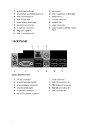
USB 3.0 connector (1) 6. USB 2.0 connectors (3) 12. blank slot (1) 15. power supply unit (PSU) release latch Back Panel Figure 2. line-in/microphone connector 7. serial connector 8. PS/2 keyboard connector 10. USB 3.0 connector 2 power connector 18. network adapter connector 4. network activity light 5. USB 2.0 connectors (2) 9. security cable slot 16. padlock ring 17. line-out connector 2. ...
USB 3.0 connector (1) 6. USB 2.0 connectors (3) 12. blank slot (1) 15. power supply unit (PSU) release latch Back Panel Figure 2. line-in/microphone connector 7. serial connector 8. PS/2 keyboard connector 10. USB 3.0 connector 2 power connector 18. network adapter connector 4. network activity light 5. USB 2.0 connectors (2) 9. security cable slot 16. padlock ring 17. line-out connector 2. ...
Page 4
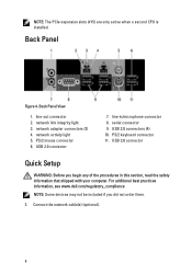
network activity light 5. For additional best practices information, see www.dell.com/regulatory_compliance NOTE: Some devices may not be included if you begin any of the procedures in /microphone connector 8. PS/2 mouse connector 6. Back Panel Figure 4. PS/2 keyboard connector 11. USB 3.0 connector Quick Setup WARNING: Before you did not order them. 1. Connect the...
network activity light 5. For additional best practices information, see www.dell.com/regulatory_compliance NOTE: Some devices may not be included if you begin any of the procedures in /microphone connector 8. PS/2 mouse connector 6. Back Panel Figure 4. PS/2 keyboard connector 11. USB 3.0 connector Quick Setup WARNING: Before you did not order them. 1. Connect the...
Page 5
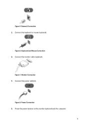
Monitor Connection 4. Power Connection 5. Keyboard and Mouse Connection 3. Figure 5. Figure 8. Figure 7. Connect the power cable(s). Connect the keyboard or mouse (optional). Press the power buttons on the monitor (optional) and the computer. 5 Figure 6. Connect the monitor cable (optional). Network Connection 2.
Monitor Connection 4. Power Connection 5. Keyboard and Mouse Connection 3. Figure 5. Figure 8. Figure 7. Connect the power cable(s). Connect the keyboard or mouse (optional). Press the power buttons on the monitor (optional) and the computer. 5 Figure 6. Connect the monitor cable (optional). Network Connection 2.
Owner's Manual
Page 45
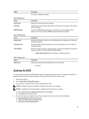
... a) Enter the Service Tag or Express Service Code and click Submit. POST Behavior Option Numlock LED Keyboard Errors POST Hotkeys Description This option is available on the bottom of all Dell products 45 Allows you have your computer's service tag or express service code, select one of the...This option is recommended to enter the BIOS Boot Option Menu. • Enable F12 Boot Option menu - Table 10. Specifies whether keyboard related errors are reported when it boots. Controls the SERR message mechanism. This option is enabled by default. This option is enabled ...
... a) Enter the Service Tag or Express Service Code and click Submit. POST Behavior Option Numlock LED Keyboard Errors POST Hotkeys Description This option is available on the bottom of all Dell products 45 Allows you have your computer's service tag or express service code, select one of the...This option is recommended to enter the BIOS Boot Option Menu. • Enable F12 Boot Option menu - Table 10. Specifies whether keyboard related errors are reported when it boots. Controls the SERR message mechanism. This option is enabled by default. This option is enabled ...


