Page 2
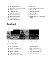
.... blank slot (1) 15. PS2/mouse connector 6. diagnostic lights (4) 11. drive activity light 7. line-out connector 2. network link integrity light 3. USB 2.0 connectors (2) 9. security cable slot 16. power supply unit (PSU) release latch Back Panel Figure 2. padlock ring 17. line-in/microphone connector 7. USB 2.0 connectors (3) 11. PS/2 keyboard connector 10. optical drive eject button...
.... blank slot (1) 15. PS2/mouse connector 6. diagnostic lights (4) 11. drive activity light 7. line-out connector 2. network link integrity light 3. USB 2.0 connectors (2) 9. security cable slot 16. power supply unit (PSU) release latch Back Panel Figure 2. padlock ring 17. line-in/microphone connector 7. USB 2.0 connectors (3) 11. PS/2 keyboard connector 10. optical drive eject button...
Page 3
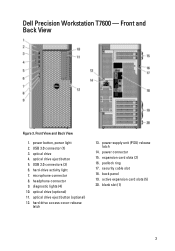
... (5) 20. headphone connector 9. diagnostic lights (4) 10. optical drive (optional) 11. hard drive access cover-release latch 13. blank slot (1) 3 optical drive eject button 5. Dell Precision Workstation T7600 - power button, power light 2. optical drive 4. padlock ring 17. Front View and Back View 1. USB 2.0 connectors (3) 6. optical drive eject button (optional) 12. security cable slot 18. microphone...
... (5) 20. headphone connector 9. diagnostic lights (4) 10. optical drive (optional) 11. hard drive access cover-release latch 13. blank slot (1) 3 optical drive eject button 5. Dell Precision Workstation T7600 - power button, power light 2. optical drive 4. padlock ring 17. Front View and Back View 1. USB 2.0 connectors (3) 6. optical drive eject button (optional) 12. security cable slot 18. microphone...
Page 6
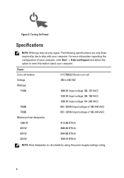
... NOTE: Offerings may vary by using the power supply wattage rating. 6 The following specifications are only those required by law to view information about your computer. Power Coin-cell battery Voltage Wattage T7600 T5600 T3600 Maximum heat dissipation 1300 W 825 W 635 W 425 W 3 V CR2032 lithium coin cell 100 to 240 VAC 1000 W (input voltage 100...
... NOTE: Offerings may vary by using the power supply wattage rating. 6 The following specifications are only those required by law to view information about your computer. Power Coin-cell battery Voltage Wattage T7600 T5600 T3600 Maximum heat dissipation 1300 W 825 W 635 W 425 W 3 V CR2032 lithium coin cell 100 to 240 VAC 1000 W (input voltage 100...
Owner's Manual
Page 3
... Computer...5 Before Working Inside Your Computer...5 Turning Off Your Computer...6 After Working Inside Your Computer...6 2 Removing and Installing Components 7 Recommended Tools...7 Removing the Power Supply Unit (PSU)...7 Installing the Power Supply Unit (PSU)...8 Removing the Cover...8 Installing the Cover...9 Removing the Optical Drive ...9 Installing the Optical Drive ...12 Removing the Thermal Sensor...12 Installing...
... Computer...5 Before Working Inside Your Computer...5 Turning Off Your Computer...6 After Working Inside Your Computer...6 2 Removing and Installing Components 7 Recommended Tools...7 Removing the Power Supply Unit (PSU)...7 Installing the Power Supply Unit (PSU)...8 Removing the Cover...8 Installing the Cover...9 Removing the Optical Drive ...9 Installing the Optical Drive ...12 Removing the Thermal Sensor...12 Installing...
Owner's Manual
Page 4
... Installing the Speaker...33 Removing the System Board...33 Installing the System Board...35 System Board Components...35 3 Additional Information...37 Memory Module Guidelines...37 Power Supply Unit (PSU) Lock...37 4 System Setup...39 Boot Sequence...39 Navigation Keys...39 System Setup Options...40 Updating the BIOS ...45 System and Setup Password... Diagnostic LEDs...51 Error Messages...54 Errors That Do Not Halt Your Computer...54 Errors That Soft Halt Your Computer...54 7 Technical Specifications...57 8 Contacting Dell...65
... Installing the Speaker...33 Removing the System Board...33 Installing the System Board...35 System Board Components...35 3 Additional Information...37 Memory Module Guidelines...37 Power Supply Unit (PSU) Lock...37 4 System Setup...39 Boot Sequence...39 Navigation Keys...39 System Setup Options...40 Updating the BIOS ...45 System and Setup Password... Diagnostic LEDs...51 Error Messages...54 Errors That Do Not Halt Your Computer...54 Errors That Soft Halt Your Computer...54 7 Technical Specifications...57 8 Contacting Dell...65
Owner's Manual
Page 7
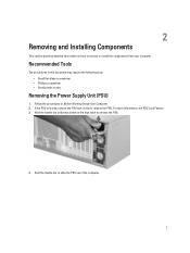
.... 7 Follow the procedures in this document may require the following tools: • Small flat-blade screwdriver • Phillips screwdriver • Small plastic scribe Removing the Power Supply Unit (PSU) 1. 2 Removing and Installing Components This section provides detailed information on the blue latch to release the PSU. Hold the handle bar to remove...
.... 7 Follow the procedures in this document may require the following tools: • Small flat-blade screwdriver • Phillips screwdriver • Small plastic scribe Removing the Power Supply Unit (PSU) 1. 2 Removing and Installing Components This section provides detailed information on the blue latch to release the PSU. Hold the handle bar to remove...

Owner's Manual
Page 8
Installing the Power Supply Unit (PSU) 1. Lay down the computer on it's right side with the latch facing up the cover-release latch. 8 Removing the Cover 1. Follow the procedures in Before Working Inside Your Computer. 2. Lift up . 3. Follow the procedures in After Working Inside Your Computer. Hold the PSU handle and slide the PSU into the computer. 2.
Installing the Power Supply Unit (PSU) 1. Lay down the computer on it's right side with the latch facing up the cover-release latch. 8 Removing the Cover 1. Follow the procedures in Before Working Inside Your Computer. 2. Lift up . 3. Follow the procedures in After Working Inside Your Computer. Hold the PSU handle and slide the PSU into the computer. 2.
Owner's Manual
Page 12
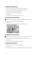
... computer. 2. Installing the Thermal Sensor NOTE: The Thermal Sensor is an optional component and your computer may not ship with it . 1. Remove the hard-drive power supply cable and the hard-drive data cable from the computer. Installing the Optical Drive 1. Removing the Thermal Sensor NOTE: The thermal sensor is an optional...
... computer. 2. Installing the Thermal Sensor NOTE: The Thermal Sensor is an optional component and your computer may not ship with it . 1. Remove the hard-drive power supply cable and the hard-drive data cable from the computer. Installing the Optical Drive 1. Removing the Thermal Sensor NOTE: The thermal sensor is an optional...
Owner's Manual
Page 14
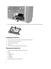
... of the hard drive cage and slide it from the latch. 14 Follow the procedures in Before Working Inside Your Computer. 2. Connect the hard drive power supply cable. 3. Removing the System Fan 1. Unthread the system board cable from the hard-drive caddy. 6. Installing the Hard Drive 1. Connect the hard drive data cable...
... of the hard drive cage and slide it from the latch. 14 Follow the procedures in Before Working Inside Your Computer. 2. Connect the hard drive power supply cable. 3. Removing the System Fan 1. Unthread the system board cable from the hard-drive caddy. 6. Installing the Hard Drive 1. Connect the hard drive data cable...
Owner's Manual
Page 37
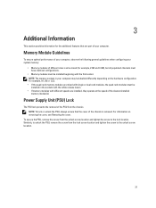
... section provides information for example, 2 GB and 4 GB), but all populated channels must have identical configurations. • Memory modules must be installed in your computer. Power Supply Unit (PSU) Lock The PSU lock prevents the removal of the slowest installed memory module(s). For example, A1, A2 or 1,2,3. • If the quad-rank...
... section provides information for example, 2 GB and 4 GB), but all populated channels must have identical configurations. • Memory modules must be installed in your computer. Power Supply Unit (PSU) Lock The PSU lock prevents the removal of the slowest installed memory module(s). For example, A1, A2 or 1,2,3. • If the quad-rank...
Owner's Manual
Page 44
... password is applied after a AC power loss. Does not allow the system to prevent users from... LAN. • LAN Only - Allows you to power on by this setting and must turn on automatically. The...the feature and no further changes will respond when AC power is set. Power Management Option AC Recovery Auto On Time Deep Sleep ...to: • Power Off (Default Setting) • Power On • Last Power State Allows you to be powered on LAN Description Allows...Setup Lockout Table 7. Default Setting: The option is connected to power up from the Standby state is enabled. • Disabled (...
... password is applied after a AC power loss. Does not allow the system to prevent users from... LAN. • LAN Only - Allows you to power on by this setting and must turn on automatically. The...the feature and no further changes will respond when AC power is set. Power Management Option AC Recovery Auto On Time Deep Sleep ...to: • Power Off (Default Setting) • Power On • Last Power State Allows you to be powered on LAN Description Allows...Setup Lockout Table 7. Default Setting: The option is connected to power up from the Standby state is enabled. • Disabled (...
Owner's Manual
Page 51
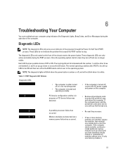
... 3, and 4, as an indicator of OFF or ON. Once the operating system starts to be ON and then turn off , connect the AC power-supply and power-on the front of the computer. The most significant bit is 51 If the computer boots, add the peripheral cards back one by one until... installed, remove the modules, then reinstall one . POST Diagnostic LED Patterns Diagnostic LEDs • The computer is either turned off or is not receiving power • The computer is booted and operating normally. • If the computer is in progress or PCI device failure was detected. • Remove ...
... 3, and 4, as an indicator of OFF or ON. Once the operating system starts to be ON and then turn off , connect the AC power-supply and power-on the front of the computer. The most significant bit is 51 If the computer boots, add the peripheral cards back one by one until... installed, remove the modules, then reinstall one . POST Diagnostic LED Patterns Diagnostic LEDs • The computer is either turned off or is not receiving power • The computer is booted and operating normally. • If the computer is in progress or PCI device failure was detected. • Remove ...
Owner's Manual
Page 52
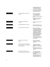
... all modules without error. • If available, install working graphics card into your computer. • Re-seat the 2x2 power connector from the power supply unit. • Ensure that no special requirements for memory module/connector placement exist. • Ensure that the display/ monitor is... supported by your computer. • Re-seat all power and data cables. • Reinstall all USB devices and check all cable...
... all modules without error. • If available, install working graphics card into your computer. • Re-seat the 2x2 power connector from the power supply unit. • Ensure that no special requirements for memory module/connector placement exist. • Ensure that the display/ monitor is... supported by your computer. • Re-seat all power and data cables. • Reinstall all USB devices and check all cable...
Owner's Manual
Page 54
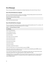
.... Table 13. - Hard Drive fan1 failure. Alert! Alert! Please contact Dell Technical support team to learn about upgrading to boot. Please refer to the RMT Event log screen in BIOS setup for a few seconds, and then continue to a higher wattage power supply. The following table lists the error messages. Front I/O Cable failure. Alert...
.... Table 13. - Hard Drive fan1 failure. Alert! Alert! Please contact Dell Technical support team to learn about upgrading to boot. Please refer to the RMT Event log screen in BIOS setup for a few seconds, and then continue to a higher wattage power supply. The following table lists the error messages. Front I/O Cable failure. Alert...
Owner's Manual
Page 61
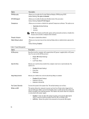
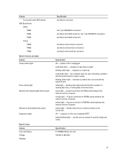
... light indicates that the computer is off - Feature Front panel audio HDA header HDD Back Panel : SATA T3600 T5600 T7600 Power T3600 T5600 T7600 Table 24. Power Feature Coin-cell battery Voltage Wattage Specification one 2x5 pin connector four 7-pin SAS/SATA connectors one 36-pin... service manual for specific diagnostic codes. computer is operating normally. blinking white light - indicates a problem has occurred with the system board or power supply. green light - solid white light - computer is in stand by. solid amber light - A good connection at 100 Mbs exists between ...
... light indicates that the computer is off - Feature Front panel audio HDA header HDD Back Panel : SATA T3600 T5600 T7600 Power T3600 T5600 T7600 Table 24. Power Feature Coin-cell battery Voltage Wattage Specification one 2x5 pin connector four 7-pin SAS/SATA connectors one 36-pin... service manual for specific diagnostic codes. computer is operating normally. blinking white light - indicates a problem has occurred with the system board or power supply. green light - solid white light - computer is in stand by. solid amber light - A good connection at 100 Mbs exists between ...
Owner's Manual
Page 62
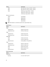
... VAC) 4113.00 BTU/hr 3086.60 BTU/hr 2484.00 BTU/hr 1450.10 BTU/hr NOTE: Heat dissipation is calculated by using the power supply wattage rating. Environmental Feature Temperature: Operating Specification 416.90 mm (16.41 inches) 414.00 mm (16.30 inches) 175.50 mm (6.91 ... Specification 10 °C to 35 °C (50 °F to 95 °F) 62 Table 26. Physical Feature T5600 Height (with feet) Height (without feet) T3600 Height (with feet) Height (without feet) T5600/T3600 Width Depth Weight (minimum): T7600 Height (with feet) Height (without feet) Width Depth Weight (minimum): Table 27.
... VAC) 4113.00 BTU/hr 3086.60 BTU/hr 2484.00 BTU/hr 1450.10 BTU/hr NOTE: Heat dissipation is calculated by using the power supply wattage rating. Environmental Feature Temperature: Operating Specification 416.90 mm (16.41 inches) 414.00 mm (16.30 inches) 175.50 mm (6.91 ... Specification 10 °C to 35 °C (50 °F to 95 °F) 62 Table 26. Physical Feature T5600 Height (with feet) Height (without feet) T3600 Height (with feet) Height (without feet) T5600/T3600 Width Depth Weight (minimum): T7600 Height (with feet) Height (without feet) Width Depth Weight (minimum): Table 27.


