
Quick Reference Guide
Page 13
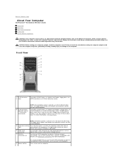
4 Connect the speakers. NOTE: If your computer has a sound card installed, connect the speakers to the card. Connect the power 5 cables and turn on the computer and monitor. Quick Reference Guide 13
4 Connect the speakers. NOTE: If your computer has a sound card installed, connect the speakers to the card. Connect the power 5 cables and turn on the computer and monitor. Quick Reference Guide 13
Quick Reference Guide
Page 17
...remain connected, such as flash memory keys, cameras, or bootable USB devices (see "Diagnostic Lights" on the diagnostic code. To exit from a power-saving state, see your User's Guide. For more information). Quick Reference Guide 17 See "Diagnostic Lights" on page 35 for a description of..., see your computer. 10 microphone connector Use the microphone connector to attach a personal computer microphone for voice or musical input into a power-saving state. It is recommended that you use the keyboard or the mouse if it into a sound or telephony program. 11 headphone ...
...remain connected, such as flash memory keys, cameras, or bootable USB devices (see "Diagnostic Lights" on the diagnostic code. To exit from a power-saving state, see your User's Guide. For more information). Quick Reference Guide 17 See "Diagnostic Lights" on page 35 for a description of..., see your computer. 10 microphone connector Use the microphone connector to attach a personal computer microphone for voice or musical input into a power-saving state. It is recommended that you use the keyboard or the mouse if it into a sound or telephony program. 11 headphone ...

Quick Reference Guide
Page 18
..., USB, and other devices into the appropriate connector (see "Back Panel Connectors" on page 19). 18 Quick Reference Guide Back View 1 2 3 1 power connector 2 card slots 3 back panel connectors Insert the power cable. Access connectors for any installed PCI, PCI-X, or PCI Express cards. the connector slots at the top and at the...
..., USB, and other devices into the appropriate connector (see "Back Panel Connectors" on page 19). 18 Quick Reference Guide Back View 1 2 3 1 power connector 2 card slots 3 back panel connectors Insert the power cable. Access connectors for any installed PCI, PCI-X, or PCI Express cards. the connector slots at the top and at the...
Quick Reference Guide
Page 21
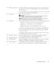
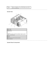
front fan card fan 5.25-inch drive bay with 3.5-inch drive panel plate 5.25-inch drive bay Quick Reference Guide 21 Inside View 1 2 7 6 1 2 3 4 5 6 7 3 5 4 power supply hard drive bay memory shroud NOTICE: The memory shroud holds the (optional) memory riser cards in order to secure the risers and to avoid damage. its thumbscrews must be sufficiently tight in place;
front fan card fan 5.25-inch drive bay with 3.5-inch drive panel plate 5.25-inch drive bay Quick Reference Guide 21 Inside View 1 2 7 6 1 2 3 4 5 6 7 3 5 4 power supply hard drive bay memory shroud NOTICE: The memory shroud holds the (optional) memory riser cards in order to secure the risers and to avoid damage. its thumbscrews must be sufficiently tight in place;

Quick Reference Guide
Page 23
...graphics riser. 1 secondary processor connector (CPU_1) 2 front fan connector (FAN_FRONT) 3 card cage fan connector (FAN_CCAG) 4 internal speaker connector (INT_SPKR) 5 power connector (POWER2) 6 IDE drive connector (IDE) 7 password jumper (PSWD) 8 auxiliary hard-drive LED connector (AUX_LED) 9 battery socket (BATTERY) 10 ...SATA connectors (SATA_0, SATA_1, SATA_2) 11 RTC reset jumper (RTCRST) 12 main power connector (POWER1) 13 hard drive connector (HDD_3) 14 hard drive connector (HDD_2) 15 hard drive connector (HDD_1) 16 hard drive connector...
...graphics riser. 1 secondary processor connector (CPU_1) 2 front fan connector (FAN_FRONT) 3 card cage fan connector (FAN_CCAG) 4 internal speaker connector (INT_SPKR) 5 power connector (POWER2) 6 IDE drive connector (IDE) 7 password jumper (PSWD) 8 auxiliary hard-drive LED connector (AUX_LED) 9 battery socket (BATTERY) 10 ...SATA connectors (SATA_0, SATA_1, SATA_2) 11 RTC reset jumper (RTCRST) 12 main power connector (POWER1) 13 hard drive connector (HDD_3) 14 hard drive connector (HDD_2) 15 hard drive connector (HDD_1) 16 hard drive connector...

Quick Reference Guide
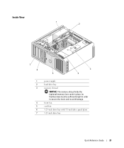
Page 34
... register failure Master DMA register failure Master interrupt mask register failure Slave interrupt mask register failure Interrupt vector loading failure Keyboard Controller Test failure NVRAM power loss Invalid NVRAM configuration Video Memory Test failure Screen initialization failure Screen retrace failure Search for video ROM failure No timer tick Shutdown failure Gate...
... register failure Master DMA register failure Master interrupt mask register failure Slave interrupt mask register failure Interrupt vector loading failure Keyboard Controller Test failure NVRAM power loss Invalid NVRAM configuration Video Memory Test failure Screen initialization failure Screen retrace failure Search for video ROM failure No timer tick Shutdown failure Gate...
Quick Reference Guide
Page 35
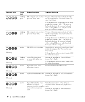
... "3," and "4" on the monitor identifying the problem. If the problem is still not resolved, contact Dell for technical assistance. The computer is in the Product Information Guide. If the power light is off, ensure that of the procedures in this section, follow the safety instructions in a normal...Guide 35 See "Error Messages" in the User's Guide for suggestions on resolving any of the power button help to identify the problem. If the problem is still not resolved, contact Dell for technical assistance. If the computer does not turn the computer off " or green. Code ...
... "3," and "4" on the monitor identifying the problem. If the problem is still not resolved, contact Dell for technical assistance. The computer is in the Product Information Guide. If the power light is off, ensure that of the procedures in this section, follow the safety instructions in a normal...Guide 35 See "Error Messages" in the User's Guide for suggestions on resolving any of the power button help to identify the problem. If the problem is still not resolved, contact Dell for technical assistance. If the computer does not turn the computer off " or green. Code ...
Quick Reference Guide
Page 36
See "Advanced Features" in your User's Guide. up " the computer. Ensure that any required power cables are detected in a plug-in connected to "wake power or "sleep" state. If the problem is still not resolved, contact Dell for technical assistance. amber A processor mismatch exists. amber A possible failure has been Verify that the processor is...
See "Advanced Features" in your User's Guide. up " the computer. Ensure that any required power cables are detected in a plug-in connected to "wake power or "sleep" state. If the problem is still not resolved, contact Dell for technical assistance. amber A processor mismatch exists. amber A possible failure has been Verify that the processor is...
Quick Reference Guide
Page 37
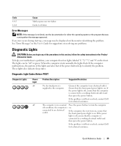
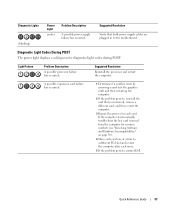
Diagnostic Light Codes During POST The power light displays a solid green for each move. 5 If the problem persists, contact Dell. Suggested Resolution Reinstall the processor and restart the computer. Light Pattern Problem Description A possible processor failure has occurred. A possible expansion card failure has occurred. 1 Determine ...
Diagnostic Light Codes During POST The power light displays a solid green for each move. 5 If the problem persists, contact Dell. Suggested Resolution Reinstall the processor and restart the computer. Light Pattern Problem Description A possible processor failure has occurred. A possible expansion card failure has occurred. 1 Determine ...
Quick Reference Guide
Page 38
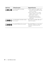
... card that you know works and restart the computer. 3 If the problem persists or the computer has integrated graphics, contact Dell. A possible floppy or hard drive failure has occurred. Reinstall all power and data cables and restart the computer. Reseat all USB devices, check cable connections, and then restart the computer. 38...
... card that you know works and restart the computer. 3 If the problem persists or the computer has integrated graphics, contact Dell. A possible floppy or hard drive failure has occurred. Reinstall all power and data cables and restart the computer. Reseat all USB devices, check cable connections, and then restart the computer. 38...
Quick Reference Guide
Page 43
...out, 19 mouse, 19 network adapter, 20 parallel, 19 power, 18 serial, 20 sound, 19-20 USB, 17, 19-20 D Dell support site, 7 Dell Diagnostics, 32-33 Dell Premier Support website, 6 diagnostic lights, 35 diagnostics beep codes, 33 Dell, 32-33 lights, 17, 35 documentation End User License Agreement... information, 6 error messages beep codes, 33 diagnostic lights, 35 H hard drive activity light, 16-17 hardware beep codes, 33 conflicts, 30 Dell Diagnostics, 32-33 Hardware Troubleshooter, 30 headphone connector, 17 Help and Support Center, 7 help file Windows Help and Support Center, 7 I IEEE...
...out, 19 mouse, 19 network adapter, 20 parallel, 19 power, 18 serial, 20 sound, 19-20 USB, 17, 19-20 D Dell support site, 7 Dell Diagnostics, 32-33 Dell Premier Support website, 6 diagnostic lights, 35 diagnostics beep codes, 33 Dell, 32-33 lights, 17, 35 documentation End User License Agreement... information, 6 error messages beep codes, 33 diagnostic lights, 35 H hard drive activity light, 16-17 hardware beep codes, 33 conflicts, 30 Dell Diagnostics, 32-33 Hardware Troubleshooter, 30 headphone connector, 17 Help and Support Center, 7 help file Windows Help and Support Center, 7 I IEEE...
Quick Reference Guide
Page 44
..., 20 network activity, 20 power, 17 M Microsoft Windows label, 6 mouse connector, 19 N network connector, 20 O operating system CD, 8 reinstalling, 8 P power button, 17 connector, 18 light, 17 problems beep codes, 33 conflicts, 30 Dell Diagnostics, 32-33 diagnostic lights..., 35 restore to previous state, 30 Product Information Guide, 6 R regulatory information, 6 ResourceCD Dell Diagnostics, 32-33 S safety instructions, 6 Service...
..., 20 network activity, 20 power, 17 M Microsoft Windows label, 6 mouse connector, 19 N network connector, 20 O operating system CD, 8 reinstalling, 8 P power button, 17 connector, 18 light, 17 problems beep codes, 33 conflicts, 30 Dell Diagnostics, 32-33 diagnostic lights..., 35 restore to previous state, 30 Product Information Guide, 6 R regulatory information, 6 ResourceCD Dell Diagnostics, 32-33 S safety instructions, 6 Service...
User Guide
Page 1
... to avoid the problem. Dell Precision™ Workstation 690 User's Guide Information About Your Computer About Your Computer Advanced Features Copying CDs and DVDs Before You Begin Computer Stand Removing the Computer Cover Chassis Intrusion Switch Memory Drives Cards Installing the Speaker (Optional) Processor Battery I/O Panel System Board Power Supply Replacing the Computer Cover...
... to avoid the problem. Dell Precision™ Workstation 690 User's Guide Information About Your Computer About Your Computer Advanced Features Copying CDs and DVDs Before You Begin Computer Stand Removing the Computer Cover Chassis Intrusion Switch Memory Drives Cards Installing the Speaker (Optional) Processor Battery I/O Panel System Board Power Supply Replacing the Computer Cover...
User Guide
Page 2
... NOTE: Hard-drive carriers is only for use in the 5.25-inch drive bays. Back to Contents Page About Your Computer Dell Precision™ Workstation 690 User's Guide Front View Back View Back Panel Connectors Inside View System Board Components CAUTION: Your computer is heavy (it has an...only for devices that you use the back USB connectors for use with a floppy drive or Media Card Reader; For more information). 8 power button It is recommended that typically remain connected, such as printers and keyboards. See your computer upright, install the computer stand. Seek ...
... NOTE: Hard-drive carriers is only for use in the 5.25-inch drive bays. Back to Contents Page About Your Computer Dell Precision™ Workstation 690 User's Guide Front View Back View Back Panel Connectors Inside View System Board Components CAUTION: Your computer is heavy (it has an...only for devices that you use the back USB connectors for use with a floppy drive or Media Card Reader; For more information). 8 power button It is recommended that typically remain connected, such as printers and keyboards. See your computer upright, install the computer stand. Seek ...

User Guide
Page 3
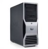
...five connector slots support full-length cards: one PCI, one PCI Express x16, one PCI Express x8 (wired as x4), and two PCI-X slots; 9 power light NOTICE: To avoid losing data, do not use the keyboard or the mouse if it is configured as a wake device in the Windows Device... Manager. Instead, perform an operating system shutdown. See Power Problems. To exit from a power-saving state, press the power button or use the power button to turn off or in a hibernation mode. ¡ Steady green - The computer is on the diagnostic code....
...five connector slots support full-length cards: one PCI, one PCI Express x16, one PCI Express x8 (wired as x4), and two PCI-X slots; 9 power light NOTICE: To avoid losing data, do not use the keyboard or the mouse if it is configured as a wake device in the Windows Device... Manager. Instead, perform an operating system shutdown. See Power Problems. To exit from a power-saving state, press the power button or use the power button to turn off or in a hibernation mode. ¡ Steady green - The computer is on the diagnostic code....
User Guide
Page 5
Inside View 1 power supply 2 hard drive bay 3 memory shroud NOTICE: The memory shroud holds the (optional) memory riser cards in order to secure the risers and to the serial port. its thumbscrews must be modified through system setup (see System Setup). If necessary, the address for this port can be sufficiently tight in place; 13 serial connector Connect a serial device, such as a handheld device, to avoid damage. 4 front fan 5 card fan 6 5.25-inch drive bay with 3.5-inch drive panel plate 7 5.25-inch drive bay System Board Components
Inside View 1 power supply 2 hard drive bay 3 memory shroud NOTICE: The memory shroud holds the (optional) memory riser cards in order to secure the risers and to the serial port. its thumbscrews must be modified through system setup (see System Setup). If necessary, the address for this port can be sufficiently tight in place; 13 serial connector Connect a serial device, such as a handheld device, to avoid damage. 4 front fan 5 card fan 6 5.25-inch drive bay with 3.5-inch drive panel plate 7 5.25-inch drive bay System Board Components

User Guide
Page 6
... fan connector (FAN_FRONT) 19 FlexBay connector (USB) 3 card cage fan connector (FAN_CCAG) 20 floppy drive (DSKT) 4 internal speaker 21 front panel connector (FRONTPANEL) connector (INT_SPKR) 5 power connector (POWER2) 22 front panel 1394 connector (FP1394) 6 IDE drive connector (IDE) 23 chassis intrusion header (INTRUDER) 7 password jumper (PSWD) 24 PCI-Express x8 card...
... fan connector (FAN_FRONT) 19 FlexBay connector (USB) 3 card cage fan connector (FAN_CCAG) 20 floppy drive (DSKT) 4 internal speaker 21 front panel connector (FRONTPANEL) connector (INT_SPKR) 5 power connector (POWER2) 22 front panel 1394 connector (FP1394) 6 IDE drive connector (IDE) 23 chassis intrusion header (INTRUDER) 7 password jumper (PSWD) 24 PCI-Express x8 card...

User Guide
Page 7
otherwise these must be left empty 34 primary processor connector (CPU_0) Cable Colors Device Hard drive (with on the graphics riser. 13 main power connector 30 (POWEsR1) NOTE: PCI-Express x8 card slot, wired as x4 (SLOT1_PCIE) 14 hard drive connector (HDD_3) 15 hard drive connector (HDD_2) 16 hard ...
otherwise these must be left empty 34 primary processor connector (CPU_0) Cable Colors Device Hard drive (with on the graphics riser. 13 main power connector 30 (POWEsR1) NOTE: PCI-Express x8 card slot, wired as x4 (SLOT1_PCIE) 14 hard drive connector (HDD_3) 15 hard drive connector (HDD_2) 16 hard ...
User Guide
Page 8
...speed (rpm) is designed to Contents Page Advanced Features Dell Precision™ Workstation 690 User's Guide LegacySelect Technology Control Manageability Security Password Protection System Setup Boot Menu Clearing Forgotten Passwords Clearing CMOS Settings Power Management Hyper-Threading and Dual-Core Technology IEEE 1394 About ... Event Cleared Boot: Failure to Boot to SNMP, DMI, and CIM industry standards. The computer power supply voltage is not functioning. Dell OpenManage™ IT Assistant IT Assistant configures, manages, and monitors computers and other devices on the...
...speed (rpm) is designed to Contents Page Advanced Features Dell Precision™ Workstation 690 User's Guide LegacySelect Technology Control Manageability Security Password Protection System Setup Boot Menu Clearing Forgotten Passwords Clearing CMOS Settings Power Management Hyper-Threading and Dual-Core Technology IEEE 1394 About ... Event Cleared Boot: Failure to Boot to SNMP, DMI, and CIM industry standards. The computer power supply voltage is not functioning. Dell OpenManage™ IT Assistant IT Assistant configures, manages, and monitors computers and other devices on the...

User Guide
Page 11
... . If Not Set is not displayed, then repeat step 3 through step 8. 9. Typing Your System Password When you type an incorrect or incomplete system password. Must power down. Certain key combinations are deleting a password, press in Assigning a System Password, starting from the field without assigning a system password, press at the prompt. Exit...
... . If Not Set is not displayed, then repeat step 3 through step 8. 9. Typing Your System Password When you type an incorrect or incomplete system password. Must power down. Certain key combinations are deleting a password, press in Assigning a System Password, starting from the field without assigning a system password, press at the prompt. Exit...


