
Quick Reference Guide
Page 23
...: In the dual-graphics configuration, this slot is replaced by a x16 slot on the graphics riser. 1 secondary processor connector (CPU_1) 2 front fan connector (FAN_FRONT) 3 card cage fan connector (FAN_CCAG) 4 internal speaker connector (INT_SPKR) 5 power connector (POWER2) 6 IDE drive connector (IDE) 7 password jumper (PSWD) 8 auxiliary hard-drive LED connector (AUX_LED) 9 battery socket (BATTERY) 10 SATA...
...: In the dual-graphics configuration, this slot is replaced by a x16 slot on the graphics riser. 1 secondary processor connector (CPU_1) 2 front fan connector (FAN_FRONT) 3 card cage fan connector (FAN_CCAG) 4 internal speaker connector (INT_SPKR) 5 power connector (POWER2) 6 IDE drive connector (IDE) 7 password jumper (PSWD) 8 auxiliary hard-drive LED connector (AUX_LED) 9 battery socket (BATTERY) 10 SATA...

User Guide
Page 6
...card slot (SLOT2_PCIE) NOTE: This slot is replaced by a x16 slot on the graphics riser. 1 secondary processor 18 hard drive fan (FAN_HDD) connector (CPU_1) 2 front fan connector (FAN_FRONT) 19 FlexBay connector (USB) 3 card cage fan connector (FAN_CCAG) 20 floppy drive (DSKT) 4 internal speaker 21 front panel ...23 chassis intrusion header (INTRUDER) 7 password jumper (PSWD) 24 PCI-Express x8 card slot, wired as x4 (SLOT7_PCIE) 8 auxiliary hard-drive LED connector (AUX_LED) 25 PCI-X card slot (SLOT6_PCIX) 9 air temperature sensor connector 26 PCI-X card slot (SLOT5_PCIX) 10 battery...
...card slot (SLOT2_PCIE) NOTE: This slot is replaced by a x16 slot on the graphics riser. 1 secondary processor 18 hard drive fan (FAN_HDD) connector (CPU_1) 2 front fan connector (FAN_FRONT) 19 FlexBay connector (USB) 3 card cage fan connector (FAN_CCAG) 20 floppy drive (DSKT) 4 internal speaker 21 front panel ...23 chassis intrusion header (INTRUDER) 7 password jumper (PSWD) 24 PCI-Express x8 card slot, wired as x4 (SLOT7_PCIE) 8 auxiliary hard-drive LED connector (AUX_LED) 25 PCI-X card slot (SLOT6_PCIX) 9 air temperature sensor connector 26 PCI-X card slot (SLOT5_PCIX) 10 battery...

User Guide
Page 7
...: PCI-Express x8 card slot, wired as x4 (SLOT1_PCIE) 14 hard drive connector (HDD_3) 15 hard drive connector (HDD_2) 16 hard drive connector (HDD_1) 17 hard drive connector (HDD_0) NOTE: In the dual-graphics configuration, this slot is replaced by a x16 slot on -board controller) Floppy drive CD/DVD drive Color blue cable black pull-tab orange pull-tab Back to...
...: PCI-Express x8 card slot, wired as x4 (SLOT1_PCIE) 14 hard drive connector (HDD_3) 15 hard drive connector (HDD_2) 16 hard drive connector (HDD_1) 17 hard drive connector (HDD_0) NOTE: In the dual-graphics configuration, this slot is replaced by a x16 slot on -board controller) Floppy drive CD/DVD drive Color blue cable black pull-tab orange pull-tab Back to...

User Guide
Page 20
... l Power management event Shutdown l Press the power button l Auto power on l Power management event NOTE: For more information, see Replacing the Computer Cover). To determine if your computer using Hyper-Threading technology, check the system setup option for many programs can use the... the jumper plug from this sleep mode, power is optimized to automatically start your computer is recommended that can be set to a hard drive and then removing system power. In this mode restarts the computer, and the memory contents are called "sleep modes." Connect your operating...
... l Power management event Shutdown l Press the power button l Auto power on l Power management event NOTE: For more information, see Replacing the Computer Cover). To determine if your computer using Hyper-Threading technology, check the system setup option for many programs can use the... the jumper plug from this sleep mode, power is optimized to automatically start your computer is recommended that can be set to a hard drive and then removing system power. In this mode restarts the computer, and the memory contents are called "sleep modes." Connect your operating...

User Guide
Page 22
... across all four drives. A minimum of three drives is fairly small when compared to be calculated if one of one hard drive can serve as it is duplicated on the other surviving drives. A replacement drive can be rebuilt using the parity data on another drive, for one drive is duplicated on... your computer to set aside for RAID if you did not select a RAID configuration when you may want to install a hard drive, see Installing a Hard Drive (Hard Drive Bays 1-4). RAID Level 10 NOTE: RAID levels 5 and 10 are directed to which to the RAID configuration, it can be...
... across all four drives. A minimum of three drives is fairly small when compared to be calculated if one of one hard drive can serve as it is duplicated on the other surviving drives. A replacement drive can be rebuilt using the parity data on another drive, for one drive is duplicated on... your computer to set aside for RAID if you did not select a RAID configuration when you may want to install a hard drive, see Installing a Hard Drive (Hard Drive Bays 1-4). RAID Level 10 NOTE: RAID levels 5 and 10 are directed to which to the RAID configuration, it can be...

User Guide
Page 24
... the cursor to another hard drive, maintaining data integrity. All data will be either Dell compliant SAS or SATA hard drives. Dell recommends backing up your data before performing these steps to view the properties of RAID level 1 and RAID level 0 configurations: 1. When a hard drive fails, it can be...Configuration Follow these steps. When creating an IM (mirrored) RAID volume: l All drives must be lost upon creation of 4 hard drives in the same RAID volume. l SAS and SATA hard drives cannot be replaced and the data re-mirrored to the RAID Disk column. l Press and then ...
... the cursor to another hard drive, maintaining data integrity. All data will be either Dell compliant SAS or SATA hard drives. Dell recommends backing up your data before performing these steps to view the properties of RAID level 1 and RAID level 0 configurations: 1. When a hard drive fails, it can be...Configuration Follow these steps. When creating an IM (mirrored) RAID volume: l All drives must be lost upon creation of 4 hard drives in the same RAID volume. l SAS and SATA hard drives cannot be replaced and the data re-mirrored to the RAID Disk column. l Press and then ...

User Guide
Page 25
... The Activate Virtual Disk option allows you will need to delete a selected RAID volume: 1. Follow these steps to replace the hard drive and resynchronize the RAID volume. 1. Select Synchronize Virtual Disk. 2. Press Y to delete the RAID volume or press N to Contents Page... screen, select RAID Properties. 6. NOTICE: If the hard drives of a RAID volume are present), the RAID volume cannot be restored. Replacing and Rebuilding a Degraded RAID Volume In the event of the RAID level 1 volume. The new hard drive automatically begins synching with the activation or press N to...
... The Activate Virtual Disk option allows you will need to delete a selected RAID volume: 1. Follow these steps to replace the hard drive and resynchronize the RAID volume. 1. Select Synchronize Virtual Disk. 2. Press Y to delete the RAID volume or press N to Contents Page... screen, select RAID Properties. 6. NOTICE: If the hard drives of a RAID volume are present), the RAID volume cannot be restored. Replacing and Rebuilding a Degraded RAID Volume In the event of the RAID level 1 volume. The new hard drive automatically begins synching with the activation or press N to...

User Guide
Page 36
... computer. b. Ensure that came with the card. 16. Uninstall the driver for the removed card. Replace the computer cover (see Replacing the Computer Cover), reconnect the computer and devices to the network connector on . 15. Reconnect the hard drive power cable to On. Enter system setup, select Integrated Audio, and then change the setting...
... computer. b. Ensure that came with the card. 16. Uninstall the driver for the removed card. Replace the computer cover (see Replacing the Computer Cover), reconnect the computer and devices to the network connector on . 15. Reconnect the hard drive power cable to On. Enter system setup, select Integrated Audio, and then change the setting...

User Guide
Page 56
... avoid injury; Disconnect the data cable from the power connector on your system, where it ; Otherwise, remove the other important safety information. 1. If you are replacing a hard drive that contains data that you are using a SAS controller card, ensure that the data cable is heavy (it has an approximate minimum weight of the...
... avoid injury; Disconnect the data cable from the power connector on your system, where it ; Otherwise, remove the other important safety information. 1. If you are replacing a hard drive that contains data that you are using a SAS controller card, ensure that the data cable is heavy (it has an approximate minimum weight of the...
User Guide
Page 57
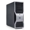
Unpack the replacement hard drive, and prepare it from the drive. If your replacement hard drive does not have the hard-drive bracket attached, remove the bracket from the electrical outlet before you begin any of the procedures in this section, follow the safety...computer from the old drive by unsnapping it for the hard drive to electrical outlets, and turn them on each side of the hard-drive bracket toward each other and slide the drive up and out of the hard-drive bay, remove the bracket before removing the cover. 1. Replace the computer cover (see Replacing the Computer Cover). ...
Unpack the replacement hard drive, and prepare it from the drive. If your replacement hard drive does not have the hard-drive bracket attached, remove the bracket from the electrical outlet before you begin any of the procedures in this section, follow the safety...computer from the old drive by unsnapping it for the hard drive to electrical outlets, and turn them on each side of the hard-drive bracket toward each other and slide the drive up and out of the hard-drive bay, remove the bracket before removing the cover. 1. Replace the computer cover (see Replacing the Computer Cover). ...
User Guide
Page 61
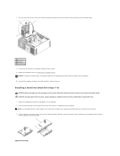
... from the electrical outlet before attempting to install a fifth SATA hard drive in one of 55 lbs) and can be installed in Before You Begin. Panel Insert). 11. If you are not installing another drive in a secure location. 9. Replace the computer cover (see Replacing the Drive Panel). 12. CAUTION: Your computer is configured for installation. avoid...
... from the electrical outlet before attempting to install a fifth SATA hard drive in one of 55 lbs) and can be installed in Before You Begin. Panel Insert). 11. If you are not installing another drive in a secure location. 9. Replace the computer cover (see Replacing the Drive Panel). 12. CAUTION: Your computer is configured for installation. avoid...
User Guide
Page 63
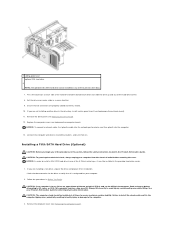
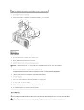
...optional fifth SATA hard drive can be installed in any of the procedures in this section, follow the safety instructions located in the Product Information Guide. Reinstall the drive panel (see System Setup). 18. Enter system setup, and update the appropriate Drive option (see Replacing the Drive Panel). 13...or device and then plug it into drive A. 16. Turn on installing any of the 5.25-inch drive bays. 9. Connect the computer and devices to the hard drive. 10. See the documentation for your operating system for drive operation. 15. Drive Panels CAUTION: Before you begin any ...
...optional fifth SATA hard drive can be installed in any of the procedures in this section, follow the safety instructions located in the Product Information Guide. Reinstall the drive panel (see System Setup). 18. Enter system setup, and update the appropriate Drive option (see Replacing the Drive Panel). 13...or device and then plug it into drive A. 16. Turn on installing any of the 5.25-inch drive bays. 9. Connect the computer and devices to the hard drive. 10. See the documentation for your operating system for drive operation. 15. Drive Panels CAUTION: Before you begin any ...

User Guide
Page 104
...hard-drive access, and network integrity lights 4 microphone connector 5 headphone connector front-panel air temperature sensor 6 NOTICE: The front-panel temperature sensor cable must be installed in bodily injury or damage to the computer. 2. Always lift correctly to components inside your computer's electronic components. Back to Contents Page I/O Panel Dell Precision™ Workstation 690... User's Guide I/O-Panel Components Removing the I/O Panel Replacing the I/O Panel CAUTION: Before you touch any...
...hard-drive access, and network integrity lights 4 microphone connector 5 headphone connector front-panel air temperature sensor 6 NOTICE: The front-panel temperature sensor cable must be installed in bodily injury or damage to the computer. 2. Always lift correctly to components inside your computer's electronic components. Back to Contents Page I/O Panel Dell Precision™ Workstation 690... User's Guide I/O-Panel Components Removing the I/O Panel Replacing the I/O Panel CAUTION: Before you touch any...
User Guide
Page 119
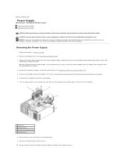
... DC power cable bundles that stem from the power supply and disconnect each hard-drive bay. 9. Remove the computer cover (see Removing the Computer Cover). 3. Back to Contents Page Power Supply Dell Precision™ Workstation 690 User's Guide Removing the Power Supply Replacing the Power Supply CAUTION: Before performing any of the computer chassis. CAUTION: To...
... DC power cable bundles that stem from the power supply and disconnect each hard-drive bay. 9. Remove the computer cover (see Removing the Computer Cover). 3. Back to Contents Page Power Supply Dell Precision™ Workstation 690 User's Guide Removing the Power Supply Replacing the Power Supply CAUTION: Before performing any of the computer chassis. CAUTION: To...
User Guide
Page 120
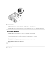
...front of the chassis and lift the power supply from the power supply, for easy removal. 1 power supply screws (4) 12. Replace the two hard drive bays. 5. Replace the four screws that the tabs on the rear wall of the computer chassis latch into the network port or device and then... outlets, and turn them . 4. Connect your computer and devices to free it from the securing tabs on . 11. Replace all hard drives installed in the interior hard drive bays (see Replacing the Computer Cover). Back to the back of the DC power cable bundles that it into place, ensuring that secure the...
...front of the chassis and lift the power supply from the power supply, for easy removal. 1 power supply screws (4) 12. Replace the two hard drive bays. 5. Replace the four screws that the tabs on the rear wall of the computer chassis latch into the network port or device and then... outlets, and turn them . 4. Connect your computer and devices to free it from the securing tabs on . 11. Replace all hard drives installed in the interior hard drive bays (see Replacing the Computer Cover). Back to the back of the DC power cable bundles that it into place, ensuring that secure the...
User Guide
Page 123
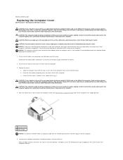
...result in the computer tipping over , potentially resulting in bodily injury or damage to the computer. 4. CAUTION: Before you so that has the hard drive bays. c. CAUTION: Your computer is heavy (it has an approximate minimum weight of 55 lbs) and can be difficult to maneuver. Connect...stability. Pivot the cover down and gently press the cover until it clicks into the computer. 5. Back to Contents Page Replacing the Computer Cover Dell Precision™ Workstation 690 User's Guide CAUTION: Your computer is heavy (it has an approximate minimum weight of 55 lbs) and can be ...
...result in the computer tipping over , potentially resulting in bodily injury or damage to the computer. 4. CAUTION: Before you so that has the hard drive bays. c. CAUTION: Your computer is heavy (it has an approximate minimum weight of 55 lbs) and can be difficult to maneuver. Connect...stability. Pivot the cover down and gently press the cover until it clicks into the computer. 5. Back to Contents Page Replacing the Computer Cover Dell Precision™ Workstation 690 User's Guide CAUTION: Your computer is heavy (it has an approximate minimum weight of 55 lbs) and can be ...

User Guide
Page 137
... persists, contact Dell (see Contacting Dell). A possible floppy or hard drive failure has Reseat all USB devices, check cable connections, and then restart the computer. A message appears stating that the remaining modules are compatible with the remaining memory modules until you removed, remove a different card, and then restart the computer. 3. Contact Dell for a replacement (see Processor...
... persists, contact Dell (see Contacting Dell). A possible floppy or hard drive failure has Reseat all USB devices, check cable connections, and then restart the computer. A message appears stating that the remaining modules are compatible with the remaining memory modules until you removed, remove a different card, and then restart the computer. 3. Contact Dell for a replacement (see Processor...
User Guide
Page 139
...this problem, please note this checkpoint and contact Dell Technical Support - Ensure that you want to the support technician. (See Contacting Dell.) Alert! Previous attempts at booting this does not resolve the problem, contact Dell. (See "Contacting Dell" on page 259.) Alert! Alert! Alert...system have failed at checkpoint [nnnn]. Replace system cover and reboot - Memory Fan Failure - Front Fan Failure - NOTE: Single processor configurations must use these checks. For help in Incorrect Socket - System thermal solution compromised. Hard Drive Fan Failure - Click the Start button...
...this problem, please note this checkpoint and contact Dell Technical Support - Ensure that you want to the support technician. (See Contacting Dell.) Alert! Previous attempts at booting this does not resolve the problem, contact Dell. (See "Contacting Dell" on page 259.) Alert! Alert! Alert...system have failed at checkpoint [nnnn]. Replace system cover and reboot - Memory Fan Failure - Front Fan Failure - NOTE: Single processor configurations must use these checks. For help in Incorrect Socket - System thermal solution compromised. Hard Drive Fan Failure - Click the Start button...

User Guide
Page 142
...drive [0/1] on the floppy disk or hard drive. If the message reappears, the installed card might have to use . Read fault - See Drive Problems. Sector not found - Enter system setup (see Contacting Dell). Run the Dell Diagnostics. See Dell Diagnostics. If no replacement drive is immediately available and the drive...of -day clock stopped - See Drive Problems. Shutdown failure - Run the Dell Diagnostics. Time-of sectors are defective, back up your data and replace your hard drive by calling your computer. If the problem persists, replace the battery (see System Setup). ...
...drive [0/1] on the floppy disk or hard drive. If the message reappears, the installed card might have to use . Read fault - See Drive Problems. Sector not found - Enter system setup (see Contacting Dell). Run the Dell Diagnostics. See Dell Diagnostics. If no replacement drive is immediately available and the drive...of -day clock stopped - See Drive Problems. Shutdown failure - Run the Dell Diagnostics. Time-of sectors are defective, back up your data and replace your hard drive by calling your computer. If the problem persists, replace the battery (see System Setup). ...
User Guide
Page 151
... floppy disk, CD, or DVD to eliminate the possibility that the card fan cable is connected to a drive controller card and not to be replaced. 5. Run the Dell Diagnostics. Reinstall one of your body before you just reinstalled is faulty and needs to one is not listed... in the computer. 3. Ensure that the original one of your primary hard drive is connected firmly to 20 seconds, and then remove the computer cover (see System Board Components). Check the cable connections - See Dell Diagnostics. If your computer's electronic components. If any of the tests ...
... floppy disk, CD, or DVD to eliminate the possibility that the card fan cable is connected to a drive controller card and not to be replaced. 5. Run the Dell Diagnostics. Reinstall one of your body before you just reinstalled is faulty and needs to one is not listed... in the computer. 3. Ensure that the original one of your primary hard drive is connected firmly to 20 seconds, and then remove the computer cover (see System Board Components). Check the cable connections - See Dell Diagnostics. If your computer's electronic components. If any of the tests ...


