
Service Manual
Page 48
... board memory sockets 1 and 2. For example, if the first and second pairs of memory sockets on the memory riser boards need to the processor) before installing modules in the other words, two sockets in a pair must contain modules of identical capacity, number of components, and speed. www....dell.com | support.dell.com • Mixed pairs of ECC and non-ECC modules all function as non-ECC. • The optional memory riser boards only support ...
... board memory sockets 1 and 2. For example, if the first and second pairs of memory sockets on the memory riser boards need to the processor) before installing modules in the other words, two sockets in a pair must contain modules of identical capacity, number of components, and speed. www....dell.com | support.dell.com • Mixed pairs of ECC and non-ECC modules all function as non-ECC. • The optional memory riser boards only support ...
Service Manual
Page 107
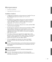
... it. 107 Upgrading the Microprocessor(s) NOTE: Dell recommends that the processor has had sufficient time to work with Dell computers. To locate the VRM and microprocessor sockets, see "System Board Components." • For dual-processor operations, both processor sockets and both VRM connectors must be populated... these components, see "System Board Components." • For single-processor operations, the processor must be installed in connector 0. If the VRMs do not match, you use only microprocessors purchased from Dell. If you are not guaranteed to cool before you are upgrading...
... it. 107 Upgrading the Microprocessor(s) NOTE: Dell recommends that the processor has had sufficient time to work with Dell computers. To locate the VRM and microprocessor sockets, see "System Board Components." • For dual-processor operations, both processor sockets and both VRM connectors must be populated... these components, see "System Board Components." • For single-processor operations, the processor must be installed in connector 0. If the VRMs do not match, you use only microprocessors purchased from Dell. If you are not guaranteed to cool before you are upgrading...

Service Manual
Page 110
... new microprocessor in the socket. b Align pin 1 of the new microprocessor with the socket, and do not use excessive force when installing the processor. 110 NOTE: Pin 1 of the microprocessor is indicated by a small triangle in one corner of the socket is indicated by a small triangle...the microprocessor aligns properly with the socket. To avoid damage, ensure that the lever on the microprocessor socket is released. www.dell.com | support.dell.com To remove the microprocessor, pull the socket lever up until the microprocessor is fully extended to the release position. See "...
... new microprocessor in the socket. b Align pin 1 of the new microprocessor with the socket, and do not use excessive force when installing the processor. 110 NOTE: Pin 1 of the microprocessor is indicated by a small triangle in one corner of the socket is indicated by a small triangle...the microprocessor aligns properly with the socket. To avoid damage, ensure that the lever on the microprocessor socket is released. www.dell.com | support.dell.com To remove the microprocessor, pull the socket lever up until the microprocessor is fully extended to the release position. See "...

Microprocessor Replacement
Page 8
... do not match, you may not start. If you are not installing a processor upgrade kit from Dell, reuse the original VRM(s). • If installing a Dell processor upgrade kit for either single or dual processors, remove and discard the original heat sink(s) and securing clips. To locate these...the VRM must be installed for it is on . If the processors do not match, the diagnostic lights will indicate an error. • If installing a Dell™ processor upgrade kit for either single or dual processors, remove and discard the original VRM(s). Then install the heat sink...
... do not match, you may not start. If you are not installing a processor upgrade kit from Dell, reuse the original VRM(s). • If installing a Dell processor upgrade kit for either single or dual processors, remove and discard the original heat sink(s) and securing clips. To locate these...the VRM must be installed for it is on . If the processors do not match, the diagnostic lights will indicate an error. • If installing a Dell™ processor upgrade kit for either single or dual processors, remove and discard the original VRM(s). Then install the heat sink...
Microprocessor Replacement
Page 9
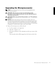
... only a technically knowledgeable person perform this procedure. b Open the computer cover. c Press down and back on the system board has turned off. NOTE: Dell recommends that the processor has had sufficient time to 20 seconds after disconnecting the computer from the computer, wait 10 to cool before you perform this light, see... tabs will disengage from the system board, verify that the standby power light on the indentations at the top corners of the shroud. CAUTION: The processor can get very hot during normal operation.
... only a technically knowledgeable person perform this procedure. b Open the computer cover. c Press down and back on the system board has turned off. NOTE: Dell recommends that the processor has had sufficient time to 20 seconds after disconnecting the computer from the computer, wait 10 to cool before you perform this light, see... tabs will disengage from the system board, verify that the standby power light on the indentations at the top corners of the shroud. CAUTION: The processor can get very hot during normal operation.

Microprocessor Replacement
Page 12
... you must position the microprocessor correctly in one corner of the new microprocessor with the socket, and do not use excessive force when installing the processor. 10 M ic r op r o ce s s or Rep l a c em e n t b Align pin 1 of the microprocessor. To avoid damage, ensure that the microprocessor aligns properly with pin 1 of the...
... you must position the microprocessor correctly in one corner of the new microprocessor with the socket, and do not use excessive force when installing the processor. 10 M ic r op r o ce s s or Rep l a c em e n t b Align pin 1 of the microprocessor. To avoid damage, ensure that the microprocessor aligns properly with pin 1 of the...
Memory Riser Board Replacement
Page 15
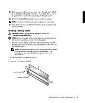
... 1 through step 13. 15 When the System Memory total is correct, exit system setup. NOTE: To access the securing clips on removing and installing the processor fan, see the Service Manual. 2 Lift the module away from the socket (see your User's Guide. 16 Turn off the computer, and attach the devices...
... 1 through step 13. 15 When the System Memory total is correct, exit system setup. NOTE: To access the securing clips on removing and installing the processor fan, see the Service Manual. 2 Lift the module away from the socket (see your User's Guide. 16 Turn off the computer, and attach the devices...
Memory Riser Board Replacement
Page 17
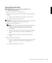
... Service Manual. a Press the securing clips of the memory socket. 3 Remove memory riser board A: NOTE: To access the securing clips on removing and installing the processor fan, see the following figure). b Lift the bracket away from socket 2. b Lift riser board B away from the chassis. a Lift the retention bracket up to disengage...
... Service Manual. a Press the securing clips of the memory socket. 3 Remove memory riser board A: NOTE: To access the securing clips on removing and installing the processor fan, see the following figure). b Lift the bracket away from socket 2. b Lift riser board B away from the chassis. a Lift the retention bracket up to disengage...
Setup and Quick Reference Guide
Page 3
Contents Finding Information and Assistance 5 Using the Dell Precision™ ResourceCD 9 Setting Up Your Computer 10 Dual Monitors 17 Frequently Asked Questions 18 Safety First-For You and Your Computer 20 Opening the Computer ... Parts 24 Adding Memory 24 Adding a Hard Drive or Externally Accessible Drive 24 Adding a PCI Expansion Card 24 Upgrading the Video Card 25 Upgrading Your Processor(s 25 Solving Problems 25 When to Use the Dell Diagnostics 26 Starting the Dell Diagnostics 27 Messages and Codes 30 Contents 3
Contents Finding Information and Assistance 5 Using the Dell Precision™ ResourceCD 9 Setting Up Your Computer 10 Dual Monitors 17 Frequently Asked Questions 18 Safety First-For You and Your Computer 20 Opening the Computer ... Parts 24 Adding Memory 24 Adding a Hard Drive or Externally Accessible Drive 24 Adding a PCI Expansion Card 24 Upgrading the Video Card 25 Upgrading Your Processor(s 25 Solving Problems 25 When to Use the Dell Diagnostics 26 Starting the Dell Diagnostics 27 Messages and Codes 30 Contents 3
Setup and Quick Reference Guide
Page 25
Upgrading Your Processor(s) Perform the preceding steps to access your User's Guide, and see "Expansion Cards." Express Service Code Service...also find online documentation about your Express Service Code and Service Tag below, and then contact Dell from the list displayed. The documentation for your computer and click Dell Documents, then click Video Adapter. For instructions on installing the card in your computer, perform...your video card upgrade kit. Solving Problems NOTE: If computer problems occur that require help from Dell support, write down your video card at support...
Upgrading Your Processor(s) Perform the preceding steps to access your User's Guide, and see "Expansion Cards." Express Service Code Service...also find online documentation about your Express Service Code and Service Tag below, and then contact Dell from the list displayed. The documentation for your computer and click Dell Documents, then click Video Adapter. For instructions on installing the card in your computer, perform...your video card upgrade kit. Solving Problems NOTE: If computer problems occur that require help from Dell support, write down your video card at support...


