Service Manual
Page 24
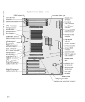
....dell.com | support.dell.com RIMM sockets (4) CD audio input connector system board speaker System Board Components VRM 0 connector microprocessor 0 with heat sink microprocessor 0 fan connector parallel and serial (2) port connectors microprocessor 1 fan connector PS/2 keyboard and mouse connectors audio connectors IEEE 1394 connector microprocessor 1 with heat sink network and Port 1 USB (2) connectors VRM 1 connector 32-bit PCI expansion card connectors (3) 64-bit PCI expansion card connectors (2) suspend-to-RAM light diskette-drive connector front panel audio connector front I/O panel...
....dell.com | support.dell.com RIMM sockets (4) CD audio input connector system board speaker System Board Components VRM 0 connector microprocessor 0 with heat sink microprocessor 0 fan connector parallel and serial (2) port connectors microprocessor 1 fan connector PS/2 keyboard and mouse connectors audio connectors IEEE 1394 connector microprocessor 1 with heat sink network and Port 1 USB (2) connectors VRM 1 connector 32-bit PCI expansion card connectors (3) 64-bit PCI expansion card connectors (2) suspend-to-RAM light diskette-drive connector front panel audio connector front I/O panel...
Service Manual
Page 47
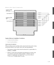
... in a pair must be upgraded in the system board sockets and not using the optional memory riser boards, observe the following guidelines: • Each memory socket on the system board must be occupied either by a RIMM or a CRIMM. • Memory sockets must contain modules of identical capacity, number of sockets. 47 See "System Board Memory Components" to -RAM light riser board B socket 4 socket 3 pair 4 socket...
... in a pair must be upgraded in the system board sockets and not using the optional memory riser boards, observe the following guidelines: • Each memory socket on the system board must be occupied either by a RIMM or a CRIMM. • Memory sockets must contain modules of identical capacity, number of sockets. 47 See "System Board Memory Components" to -RAM light riser board B socket 4 socket 3 pair 4 socket...
Service Manual
Page 66
... you installed a hard drive, update the drive settings under Secondary Drives to Auto. • If you installed a hard drive, partition and logically format the drive before proceeding to enable your finger until the insert snaps free of drives, see the drive's documentation for instructions on testing the drive. NOTE: If you install a tape drive, refer to the documentation that it is operating properly. • If the drive you installed is a hard drive, run the Dell Diagnostics to be displayed at...
... you installed a hard drive, update the drive settings under Secondary Drives to Auto. • If you installed a hard drive, partition and logically format the drive before proceeding to enable your finger until the insert snaps free of drives, see the drive's documentation for instructions on testing the drive. NOTE: If you install a tape drive, refer to the documentation that it is operating properly. • If the drive you installed is a hard drive, run the Dell Diagnostics to be displayed at...
Service Manual
Page 74
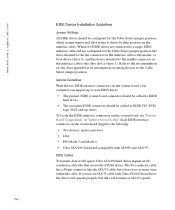
... it has twice as many wires within the cable. When two EIDE drives are connected to a single EIDE interface cable and are configured for the Cable Select jumper position, the drive attached to the last connector on the interface cable is the slave device (drive 1). www.dell.com | support.dell.com EIDE Device Installation Guidelines Jumper Settings All EIDE drives should be configured for the Cable Select jumper position, which assigns master and slave...
... it has twice as many wires within the cable. When two EIDE drives are connected to a single EIDE interface cable and are configured for the Cable Select jumper position, the drive attached to the last connector on the interface cable is the slave device (drive 1). www.dell.com | support.dell.com EIDE Device Installation Guidelines Jumper Settings All EIDE drives should be configured for the Cable Select jumper position, which assigns master and slave...

Service Manual
Page 76
... | support.dell.com SCSI devices installed by Dell are not guaranteed to work with any optional SCSI device you attach additional optional SCSI devices, refer to the documentation for each device for a SCSI ID number and disable termination, if necessary. • To use an external SCSI device, you disable termination on all devices in your computer. You do not need to the connector on the back of the external SCSI cable to set...
... | support.dell.com SCSI devices installed by Dell are not guaranteed to work with any optional SCSI device you attach additional optional SCSI devices, refer to the documentation for each device for a SCSI ID number and disable termination, if necessary. • To use an external SCSI device, you disable termination on all devices in your computer. You do not need to the connector on the back of the external SCSI cable to set...
Service Manual
Page 77
... board or the SCSI controller card installed in system setup if no EIDE hard drives are not guaranteed to the various drives. • After installing a SCSI hard drive, Primary Drive 0 and Primary Drive 1 should be set to Auto. • You may need to use . If you use only SCSI cables purchased from Dell. The remaining connectors on the second EIDE channel, such as tape drives, CD drives, and some hard drives) use a 68-pin cable. The remaining connectors...
... board or the SCSI controller card installed in system setup if no EIDE hard drives are not guaranteed to the various drives. • After installing a SCSI hard drive, Primary Drive 0 and Primary Drive 1 should be set to Auto. • You may need to use . If you use only SCSI cables purchased from Dell. The remaining connectors on the second EIDE channel, such as tape drives, CD drives, and some hard drives) use a 68-pin cable. The remaining connectors...
Service Manual
Page 86
... rear of the expansion cards can prevent the computer cover from the expansioncard cooling fan. 9 Close the computer cover. 10 Stand the computer upright. 11 Reconnect the computer and devices to Off. Enter system setup and reset the Chassis Intrusion option as described in your User's Guide. 12 If you installed an add-in network adapter, perform the following steps: a Enter system setup, select Integrated Devices and change the setting for Sound...
... rear of the expansion cards can prevent the computer cover from the expansioncard cooling fan. 9 Close the computer cover. 10 Stand the computer upright. 11 Reconnect the computer and devices to Off. Enter system setup and reset the Chassis Intrusion option as described in your User's Guide. 12 If you installed an add-in network adapter, perform the following steps: a Enter system setup, select Integrated Devices and change the setting for Sound...

Service Manual
Page 112
... the devices to the computer and electrical outlets. www.dell.com | support.dell.com NOTICE: Carefully align the heat sink with the retention base before making contact with the base to help avoid spreading the thermal grease to be displayed at the next computer start-up: ALERT! Then, press down on . Enter system setup and reset the Chassis Intrusion option as...
... the devices to the computer and electrical outlets. www.dell.com | support.dell.com NOTICE: Carefully align the heat sink with the retention base before making contact with the base to help avoid spreading the thermal grease to be displayed at the next computer start-up: ALERT! Then, press down on . Enter system setup and reset the Chassis Intrusion option as...

Microprocessor Replacement
Page 14
... retention base (see your User's Guide. 12 M ic r op r o ce s s or Rep l a c em e n t w w w.d el l.co m | su p po rt. c For each of the replacement metal clips that the top line in the System Data area correctly identifies the new microprocessor. 11 Exit system setup, turn it on. NOTE: If enabled, the Chassis Intrusion option will cause the following message...
... retention base (see your User's Guide. 12 M ic r op r o ce s s or Rep l a c em e n t w w w.d el l.co m | su p po rt. c For each of the replacement metal clips that the top line in the System Data area correctly identifies the new microprocessor. 11 Exit system setup, turn it on. NOTE: If enabled, the Chassis Intrusion option will cause the following message...

Setup and Quick Reference Guide
Page 12
... optional modem, connect the phone line to the network adapter. Voltage from telephone communications can cause damage to the modem. NOTE: Your computer has an integrated network adapter. However, if your computer has a network expansion card installed, connect the network cable to the network card, not to the network adapter. NOTICE: Do not connect a modem cable to the connector on the computer back panel. network cable modem cable 12 Setup and Quick Re ference Guide...
... optional modem, connect the phone line to the network adapter. Voltage from telephone communications can cause damage to the modem. NOTE: Your computer has an integrated network adapter. However, if your computer has a network expansion card installed, connect the network cable to the network card, not to the network adapter. NOTICE: Do not connect a modem cable to the connector on the computer back panel. network cable modem cable 12 Setup and Quick Re ference Guide...
Setup and Quick Reference Guide
Page 14
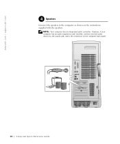
However, if your computer has an audio expansion card installed, connect external audio devices to the sound card, not to the computer as shown on the computer back panel. 14 Setup and Quick Re ference Guide NOTE: Your computer has an integrated audio controller. www.dell.com | support.dell.com 4 Speakers Connect the speakers to the connectors on the instructions supplied with the speakers.
However, if your computer has an audio expansion card installed, connect external audio devices to the sound card, not to the computer as shown on the computer back panel. 14 Setup and Quick Re ference Guide NOTE: Your computer has an integrated audio controller. www.dell.com | support.dell.com 4 Speakers Connect the speakers to the connectors on the instructions supplied with the speakers.
Setup and Quick Reference Guide
Page 16
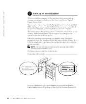
... and Express Service Code. You can find this above the service tag on your system's internal and external devices. NOTE: For more information, access your computer documentation from the Dell Precision ResourceCD. 16 Setup and Quick Re ference Guide For future reference, write the number below: Product Key (ID or COA For more information on the desktop or from the User's Guides icon on setting up messages...
... and Express Service Code. You can find this above the service tag on your system's internal and external devices. NOTE: For more information, access your computer documentation from the Dell Precision ResourceCD. 16 Setup and Quick Re ference Guide For future reference, write the number below: Product Key (ID or COA For more information on the desktop or from the User's Guides icon on setting up messages...
Setup and Quick Reference Guide
Page 18
... see "Technical Specifications." click the User's Guides icon Click User's Guides in the Topic pull-down menu, click Start button and select Help the user's guide appropriate and Support. See "Limited Warranty and Return Policy" in your User's Guide. Dell Precision ResourceCD. See the for more information. Try... and search using the keywords Product Key. Click User's Guides in the on your User's Guide. At the operating system, double- User's Guide. Or try the Dell Precision ResourceCD...
... see "Technical Specifications." click the User's Guides icon Click User's Guides in the Topic pull-down menu, click Start button and select Help the user's guide appropriate and Support. See "Limited Warranty and Return Policy" in your User's Guide. Dell Precision ResourceCD. See the for more information. Try... and search using the keywords Product Key. Click User's Guides in the on your User's Guide. At the operating system, double- User's Guide. Or try the Dell Precision ResourceCD...
Setup and Quick Reference Guide
Page 19
... "Removing and Installing Parts." Go to access your desktop or click the Start button and select Help and Support. At the Welcome page, click Dell Documents. Setup and Quick Reference Guide 19 Start button, and then select click the user's guide monitor. The monitor is blank The computer is located in the Topic pull-down menu, click with general usage, installation, and troubleshooting instructions. the user's guide appropriate Depending on your User's Guide. See "Power Management" in your operating...
... "Removing and Installing Parts." Go to access your desktop or click the Start button and select Help and Support. At the Welcome page, click Dell Documents. Setup and Quick Reference Guide 19 Start button, and then select click the user's guide monitor. The monitor is blank The computer is located in the Topic pull-down menu, click with general usage, installation, and troubleshooting instructions. the user's guide appropriate Depending on your User's Guide. See "Power Management" in your operating...
Setup and Quick Reference Guide
Page 20
... Click User's Guides in "Inside Your Dell Precision ResourceCD. How do I installed 4 GB of my memory appear to support.dell.com. Make selections appropriate for your operating system. Go to access your computer, do I install See the interior service label Go to service the computer except as explained in this guide and elsewhere in your computer, and then Memory" under the see "Removing and Installing Topic pull-down menu, click Start button...
... Click User's Guides in "Inside Your Dell Precision ResourceCD. How do I installed 4 GB of my memory appear to support.dell.com. Make selections appropriate for your operating system. Go to access your computer, do I install See the interior service label Go to service the computer except as explained in this guide and elsewhere in your computer, and then Memory" under the see "Removing and Installing Topic pull-down menu, click Start button...
Setup and Quick Reference Guide
Page 24
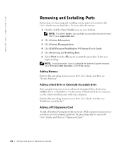
... Interconnect (PCI) expansion card, such as a portable document format (PDF) file at support.dell.com. 2 Click System Information. 3 Click System Documentation. 4 Click Dell Precision WorkStation 530 System User's Guide. 5 Click Removing and Installing Parts. 6 Select Print from the File menu to access the User's Guide, and then see the order form that came with the Internet Explorer browser, select Print all linked documents in the User's Guide on your hard drive. To...
... Interconnect (PCI) expansion card, such as a portable document format (PDF) file at support.dell.com. 2 Click System Information. 3 Click System Documentation. 4 Click Dell Precision WorkStation 530 System User's Guide. 5 Click Removing and Installing Parts. 6 Select Print from the File menu to access the User's Guide, and then see the order form that came with the Internet Explorer browser, select Print all linked documents in the User's Guide on your hard drive. To...
Setup and Quick Reference Guide
Page 26
... information, see "Diagnostic Lights" on the front of current or possible failure. The Dell Precision ResourceCD contains Dell Diagnostics that tests various components on page 37. Running the Dell Diagnostics may help you resolve the problem without contacting Dell. www.dell.com | support.dell.com Dell provides tools to help you solve problems. The tools listed in your User's Guide and run • Display test results 26 Setup and Quick Re ference Guide Your computer includes...
... information, see "Diagnostic Lights" on the front of current or possible failure. The Dell Precision ResourceCD contains Dell Diagnostics that tests various components on page 37. Running the Dell Diagnostics may help you resolve the problem without contacting Dell. www.dell.com | support.dell.com Dell provides tools to help you solve problems. The tools listed in your User's Guide and run • Display test results 26 Setup and Quick Re ference Guide Your computer includes...
Setup and Quick Reference Guide
Page 28
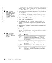
... is located at the top of each test screen. You can customize the tests you want to run . Then shut down your computer through the Start menu and try again. 3 When the boot device list appears, highlight IDE CD-ROM Device and press . 4 Select the IDE CD-ROM Device option from the CD boot menu. 5 Select the Boot from CD-ROM option from the menu that appears. 6 Type 1 to start the Dell Diagnostics. 8 Select Run the...
... is located at the top of each test screen. You can customize the tests you want to run . Then shut down your computer through the Start menu and try again. 3 When the boot device list appears, highlight IDE CD-ROM Device and press . 4 Select the IDE CD-ROM Device option from the CD boot menu. 5 Select the Boot from CD-ROM option from the menu that appears. 6 Type 1 to start the Dell Diagnostics. 8 Select Run the...
Setup and Quick Reference Guide
Page 30
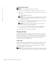
... the diagnostic lights to see if the specific problem is already on, restart it). 2 When F2 = Setup appears in the Boot First Device: menu option and press to move it after running the Dell Diagnostics. 4 Use the arrow keys to highlight CD Device in the upper-right corner of the list. 5 Press to them. www.dell.com | support.dell.com Changing the Boot Sequence NOTE: For more information, see your User's Guide. 1 Turn on...
... the diagnostic lights to see if the specific problem is already on, restart it). 2 When F2 = Setup appears in the Boot First Device: menu option and press to move it after running the Dell Diagnostics. 4 Use the arrow keys to highlight CD Device in the upper-right corner of the list. 5 Press to them. www.dell.com | support.dell.com Changing the Boot Sequence NOTE: For more information, see your User's Guide. 1 Turn on...
Setup and Quick Reference Guide
Page 31
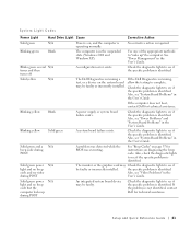
... for technical assistance. Check the diagnostic lights to see if the specific problem is identified. Also, see "Power Problems" and "System Board Problems" in the User's Guide. Also, see "System Board Problems" in the User's Guide. System Light Codes Power Light Hard Drive Light Cause Corrective Action Solid green N/A Power is on diagnosing the beep code. Solid yellow N/A The Dell Diagnostics is running a test, or a device on the system board may be faulty or incorrectly installed. Check the diagnostic lights to see "Video Problems" in the User's Guide...
... for technical assistance. Check the diagnostic lights to see if the specific problem is identified. Also, see "Power Problems" and "System Board Problems" in the User's Guide. Also, see "System Board Problems" in the User's Guide. System Light Codes Power Light Hard Drive Light Cause Corrective Action Solid green N/A Power is on diagnosing the beep code. Solid yellow N/A The Dell Diagnostics is running a test, or a device on the system board may be faulty or incorrectly installed. Check the diagnostic lights to see "Video Problems" in the User's Guide...


