Diagnostics and Troubleshooting Guide (.pdf)
Page 5
...Safety Instructions Use the following safety guidelines: • To help avoid damaging your computer, be sure the voltage selection switch on the power supply is set to help protect your computer system from sudden, transient increases and decreases in Chapter 6. • Do not push any...guidelines to help ensure proper grounding. If the computer gets wet, see "Troubleshooting a Wet Computer" in electrical power, use a surge suppressor, line conditioner, or uninterruptible power supply (UPS). • Be sure nothing rests on your computer system's cables and that the cables are not ...
...Safety Instructions Use the following safety guidelines: • To help avoid damaging your computer, be sure the voltage selection switch on the power supply is set to help protect your computer system from sudden, transient increases and decreases in Chapter 6. • Do not push any...guidelines to help ensure proper grounding. If the computer gets wet, see "Troubleshooting a Wet Computer" in electrical power, use a surge suppressor, line conditioner, or uninterruptible power supply (UPS). • Be sure nothing rests on your computer system's cables and that the cables are not ...

Diagnostics and Troubleshooting Guide (.pdf)
Page 76
... Go to step 14. 6-8 Diagnostics and Troubleshooting Guide Yes. Remove all the AC power cables from a defective system board component, a faulty power supply, or a defective component connected to AC power, and turn off the system, disconnect it from the computer. 2. Go to step ...7. See Chapter 7, "Getting Help," for instructions. 9. Yes. Insert the Dell Diagnostics Diskette into drive A, and ...
... Go to step 14. 6-8 Diagnostics and Troubleshooting Guide Yes. Remove all the AC power cables from a defective system board component, a faulty power supply, or a defective component connected to AC power, and turn off the system, disconnect it from the computer. 2. Go to step ...7. See Chapter 7, "Getting Help," for instructions. 9. Yes. Insert the Dell Diagnostics Diskette into drive A, and ...
Diagnostics and Troubleshooting Guide (.pdf)
Page 77
...; A diskette drive may be improperly configured. • The diskette drive or tape drive is faulty. • The computer's power supply is configured correctly for the installed diskette drive(s). Swap the keyboard with one drive can affect the entire subsystem. Troubleshooting the Diskette/... is resolved. Troubleshooting a Diskette-Drive Subsystem If you receive a system error message indicating a diskette drive problem, insert the Dell Diagnostics Diskette into drive A, and reboot the system by any computer that the diskette/tape drive subsystem is operating properly, follow...
...; A diskette drive may be improperly configured. • The diskette drive or tape drive is faulty. • The computer's power supply is configured correctly for the installed diskette drive(s). Swap the keyboard with one drive can affect the entire subsystem. Troubleshooting the Diskette/... is resolved. Troubleshooting a Diskette-Drive Subsystem If you receive a system error message indicating a diskette drive problem, insert the Dell Diagnostics Diskette into drive A, and reboot the system by any computer that the diskette/tape drive subsystem is operating properly, follow...

Diagnostics and Troubleshooting Guide (.pdf)
Page 83
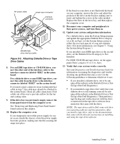
Correct the jumper settings for the drive and/or controller card as instructed by the documentation for the drive spinning up after the power supply turns on your hard-disk drive. 1. Go to step 10. 10. Before you proceed, make sure you hear the drive spinning up all the...card, see the documentation for more SCSI hard-disk drives and does not contain a SCSI backplane board. Checking Inside Your Computer 6-15 Go to AC power, reconnect any required SCSI device drivers are required and how they should be installed and configured. You have fixed the problem. Yes. No. No....
Correct the jumper settings for the drive and/or controller card as instructed by the documentation for the drive spinning up after the power supply turns on your hard-disk drive. 1. Go to step 10. 10. Before you proceed, make sure you hear the drive spinning up all the...card, see the documentation for more SCSI hard-disk drives and does not contain a SCSI backplane board. Checking Inside Your Computer 6-15 Go to AC power, reconnect any required SCSI device drivers are required and how they should be installed and configured. You have fixed the problem. Yes. No. No....
Diagnostics and Troubleshooting Guide (.pdf)
Page 126
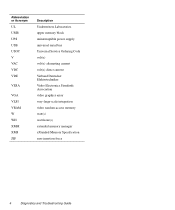
Abbreviation or Acronym UL UMB UPS USB USOC V VAC VDC VDE VESA VGA VLSI VRAM W WH XMM XMS ZIF Description Underwriters Laboratories upper memory block uninterruptible power supply universal serial bus Universal Service Ordering Code volt(s) volt(s) alternating current volt(s) direct current Verband Deutscher Elektrotechniker Video Electronics Standards Association video graphics array very-large-scale integration video random-access memory watt(s) watt-hour(s) extended memory manager eXtended Memory Specification zero insertion force 4 Diagnostics and Troubleshooting Guide
Abbreviation or Acronym UL UMB UPS USB USOC V VAC VDC VDE VESA VGA VLSI VRAM W WH XMM XMS ZIF Description Underwriters Laboratories upper memory block uninterruptible power supply universal serial bus Universal Service Ordering Code volt(s) volt(s) alternating current volt(s) direct current Verband Deutscher Elektrotechniker Video Electronics Standards Association video graphics array very-large-scale integration video random-access memory watt(s) watt-hour(s) extended memory manager eXtended Memory Specification zero insertion force 4 Diagnostics and Troubleshooting Guide
User's Guide (.pdf)
Page 5
... increases and decreases in most of your computer; If you must use an extension cable, use a surge suppressor, line conditioner, or uninterruptible power supply (UPS). • Be sure nothing rests on a bed, sofa, or rug. Ergonomic Computing Habits WARNING: Improper or prolonged keyboard use ...some Far Eastern countries such as you work. Safety Instructions Use the following safety guidelines to help protect your computer system from Dell and other sources) to help you correctly position your keyboard. If the computer gets wet, consult your Diagnostics and Troubleshooting Guide....
... increases and decreases in most of your computer; If you must use an extension cable, use a surge suppressor, line conditioner, or uninterruptible power supply (UPS). • Be sure nothing rests on a bed, sofa, or rug. Ergonomic Computing Habits WARNING: Improper or prolonged keyboard use ...some Far Eastern countries such as you work. Safety Instructions Use the following safety guidelines to help protect your computer system from Dell and other sources) to help you correctly position your keyboard. If the computer gets wet, consult your Diagnostics and Troubleshooting Guide....

User's Guide (.pdf)
Page 16
...Connecting to a Network 5-2 Network Cable Requirements 5-2 Configuring the NIC 5-2 Windows NT 4.0 NIC Driver 5-2 Windows 95 NIC Driver 5-3 Dell-Installed Windows 95 Service Release 2 5-3 Windows 95 Operating Systems Not Installed by Dell 5-4 Using the NDIS 2.01 Driver With Windows 95 5-5 Chapter 6 Using the Integrated Audio Controller 6-1 Connecting Audio Devices 6-1 Speakers ... Your Computer 7-3 Removing and Replacing the Expansion-Card Cage 7-4 Removing the Expansion-Card Cage 7-4 Replacing the Expansion-Card Cage 7-5 Rotating the Power Supply Away From the System Board 7-5 xvi
...Connecting to a Network 5-2 Network Cable Requirements 5-2 Configuring the NIC 5-2 Windows NT 4.0 NIC Driver 5-2 Windows 95 NIC Driver 5-3 Dell-Installed Windows 95 Service Release 2 5-3 Windows 95 Operating Systems Not Installed by Dell 5-4 Using the NDIS 2.01 Driver With Windows 95 5-5 Chapter 6 Using the Integrated Audio Controller 6-1 Connecting Audio Devices 6-1 Speakers ... Your Computer 7-3 Removing and Replacing the Expansion-Card Cage 7-4 Removing the Expansion-Card Cage 7-4 Replacing the Expansion-Card Cage 7-5 Rotating the Power Supply Away From the System Board 7-5 xvi
User's Guide (.pdf)
Page 19
... D-2 Cleaning Drives D-3 Environmental Factors D-3 Temperature D-3 Humidity D-3 Altitude D-4 Dust and Particles D-4 Corrosion D-4 ESD D-4 Electromagnetic and Radio Frequency Interference D-4 Magnetism D-5 Shock and Vibration D-5 Power Source Interruptions D-5 Power Protection Devices D-6 Surge Protectors D-6 Line Conditioners D-6 Uninterruptible Power Supply D-6 Appendix E Regulatory Notices E-1 FCC Notices (U.S. Only E-1 Class A E-1 Class B E-2 IC Notice (Canada Only E-2 EN 55022 Compliance (Czech Republic Only E-3 CE Notice...
... D-2 Cleaning Drives D-3 Environmental Factors D-3 Temperature D-3 Humidity D-3 Altitude D-4 Dust and Particles D-4 Corrosion D-4 ESD D-4 Electromagnetic and Radio Frequency Interference D-4 Magnetism D-5 Shock and Vibration D-5 Power Source Interruptions D-5 Power Protection Devices D-6 Surge Protectors D-6 Line Conditioners D-6 Uninterruptible Power Supply D-6 Appendix E Regulatory Notices E-1 FCC Notices (U.S. Only E-1 Class A E-1 Class B E-2 IC Notice (Canada Only E-2 EN 55022 Compliance (Czech Republic Only E-3 CE Notice...

User's Guide (.pdf)
Page 21
... 7-2 Replacing the Computer Cover 7-3 Computer Orientation View 7-3 Inside the Chassis 7-4 Removing the Expansion-Card Cage 7-5 Rotating the Power Supply 7-5 System Board Features 8-1 Expansion Cards 8-2 Riser-Board Expansion-Card Connectors 8-2 Removing the Filler Bracket 8-3 Installing an Expansion ...Cartridge/Heat Sink Assembly Removal 8-7 System Battery and Battery Socket 8-9 Drive Locations 9-1 Removing a Front-Panel Insert 9-2 DC Power Cable Connector 9-2 Drive Interface Connectors 9-3 Attaching Diskette Drive or Tape Drive Cables 9-5 Installing a Drive on the 3.5-Inch ...
... 7-2 Replacing the Computer Cover 7-3 Computer Orientation View 7-3 Inside the Chassis 7-4 Removing the Expansion-Card Cage 7-5 Rotating the Power Supply 7-5 System Board Features 8-1 Expansion Cards 8-2 Riser-Board Expansion-Card Connectors 8-2 Removing the Filler Bracket 8-3 Installing an Expansion ...Cartridge/Heat Sink Assembly Removal 8-7 System Battery and Battery Socket 8-9 Drive Locations 9-1 Removing a Front-Panel Insert 9-2 DC Power Cable Connector 9-2 Drive Interface Connectors 9-3 Attaching Diskette Drive or Tape Drive Cables 9-5 Installing a Drive on the 3.5-Inch ...
User's Guide (.pdf)
Page 27
... the system, unplug the AC power cable from the power supply to your computer is maintained from its operation. Front Panel Back Panel Your computer's back panel contains various ports and connectors for diskette drives and tape drives are described in the following indicators and controls (see "Dell AutoShutdown Service" in Chapter 2.) NOTE: A Display...
... the system, unplug the AC power cable from the power supply to your computer is maintained from its operation. Front Panel Back Panel Your computer's back panel contains various ports and connectors for diskette drives and tape drives are described in the following indicators and controls (see "Dell AutoShutdown Service" in Chapter 2.) NOTE: A Display...
User's Guide (.pdf)
Page 69
...FOR YOUR PERSONAL SAFETY AND PROTECTION OF YOUR EQUIPMENT Before starting to system board features; and it shows how to rotate the power supply to gain access to work on your computer is not repeated in detail elsewhere in - Read this section carefully, because the... touch an unpainted metal surface on the computer chassis, such as the power supply, before disconnecting the peripheral or removing the component to avoid possible damage to dissipate any static electricity that you install Dell hardware options. It describes how to install options inside your computer. Safety...
...FOR YOUR PERSONAL SAFETY AND PROTECTION OF YOUR EQUIPMENT Before starting to system board features; and it shows how to rotate the power supply to gain access to work on your computer is not repeated in detail elsewhere in - Read this section carefully, because the... touch an unpainted metal surface on the computer chassis, such as the power supply, before disconnecting the peripheral or removing the component to avoid possible damage to dissipate any static electricity that you install Dell hardware options. It describes how to install options inside your computer. Safety...
User's Guide (.pdf)
Page 71
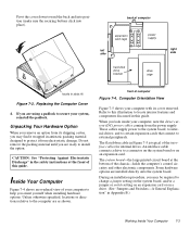
...drive. (See "Jumpers and Switches-A General Explanation" in the safety instructions at the bottom of computer expansion card cage left side power supply hard-disk drive bracket drive cage right side hooks in antistatic packing material designed to install the option. If you are ready to...Computer Figure 7-4 shows an overhead view of computer Figure 7-4. Do not remove the packing material until you may find it from the power supply. to secure your computer with its shipping carton, you orient yourself when installing hardware options. Pivot the cover down toward the back...
...drive. (See "Jumpers and Switches-A General Explanation" in the safety instructions at the bottom of computer expansion card cage left side power supply hard-disk drive bracket drive cage right side hooks in antistatic packing material designed to install the option. If you are ready to...Computer Figure 7-4 shows an overhead view of computer Figure 7-4. Do not remove the packing material until you may find it from the power supply. to secure your computer with its shipping carton, you orient yourself when installing hardware options. Pivot the cover down toward the back...

User's Guide (.pdf)
Page 72
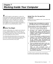
...found earlier in jack line-out jack expansion-card cage system board video connector Removing and Replacing the Expansion-Card Cage Your Dell computer has a removable expansion-card cage, which greatly simplifies many installation procedures by allowing you to expansion cards through the ...installed expansion cards together. Check any cables that will not reach to remove the expansioncard cage: 1. DC power cable diskette/tape drive interface cable power supply AC power receptacle voltage selection switch drive in upper bay hard-disk drive fan guard padlock ring parallel port connector ...
...found earlier in jack line-out jack expansion-card cage system board video connector Removing and Replacing the Expansion-Card Cage Your Dell computer has a removable expansion-card cage, which greatly simplifies many installation procedures by allowing you to expansion cards through the ...installed expansion cards together. Check any cables that will not reach to remove the expansioncard cage: 1. DC power cable diskette/tape drive interface cable power supply AC power receptacle voltage selection switch drive in upper bay hard-disk drive fan guard padlock ring parallel port connector ...
User's Guide (.pdf)
Page 73
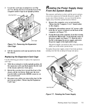
... locate the securing tab (labeled "RELEASE") at the back-left corner of the previous procedure, "Removing the ExpansionCard Cage." Rotating the Power Supply Working Inside Your Computer 7-5 Rotate the lever toward the front of the computer (see Figure 7-5). 3. Locate the card-cage securing lever ...the upright position, fit the expansion-card cage flush against the left to disengage the power supply, and rotate the power supply to the right until it stops. To replace the power supply, rotate it into place. Replacing the Expansion-Card Cage Use the following procedure to ...
... locate the securing tab (labeled "RELEASE") at the back-left corner of the previous procedure, "Removing the ExpansionCard Cage." Rotating the Power Supply Working Inside Your Computer 7-5 Rotate the lever toward the front of the computer (see Figure 7-5). 3. Locate the card-cage securing lever ...the upright position, fit the expansion-card cage flush against the left to disengage the power supply, and rotate the power supply to the right until it stops. To replace the power supply, rotate it into place. Replacing the Expansion-Card Cage Use the following procedure to ...

User's Guide (.pdf)
Page 79
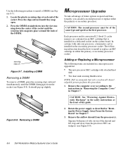
...Run the Dell Diagnostics to enter the System Setup program, and check the System Memory category in their sockets. Installing a DIMM If a DIMM is correct, press the key to exit the System Setup program. 9. Determine the DIMM sockets into place. 6. Remove the computer cover, rotate the power supply, and..., reconnect your Diagnostics and Troubleshooting Guide for information on . Install or replace DIMMs as described in "Rotating the Power Supply Away From the System Board" in their sockets. See your computer and peripherals to reach the desired memory total. Table 8-1. Rotate...
...Run the Dell Diagnostics to enter the System Setup program, and check the System Memory category in their sockets. Installing a DIMM If a DIMM is correct, press the key to exit the System Setup program. 9. Determine the DIMM sockets into place. 6. Remove the computer cover, rotate the power supply, and..., reconnect your Diagnostics and Troubleshooting Guide for information on . Install or replace DIMMs as described in "Rotating the Power Supply Away From the System Board" in their sockets. See your computer and peripherals to reach the desired memory total. Table 8-1. Rotate...
User's Guide (.pdf)
Page 80
... the airflow shroud from the socket (see Figure 8-7): 1. In systems with attached heat sink • Two heat sink securing thumbscrews NOTE: Dell recommends that is installed in Chapter 7. The following subsection describes how to the instructions in "Removing the Computer Cover" in the secondary processor ... from the processor(s). Locate the plastic securing clips at the front of the same type and speed as described in "Rotating the Power Supply Away From the System Board" in an SEC cartridge that only a technically knowledgeable person perform this guide. 2. Press the clips ...
... the airflow shroud from the socket (see Figure 8-7): 1. In systems with attached heat sink • Two heat sink securing thumbscrews NOTE: Dell recommends that is installed in Chapter 7. The following subsection describes how to the instructions in "Removing the Computer Cover" in the secondary processor ... from the processor(s). Locate the plastic securing clips at the front of the same type and speed as described in "Rotating the Power Supply Away From the System Board" in an SEC cartridge that only a technically knowledgeable person perform this guide. 2. Press the clips ...
User's Guide (.pdf)
Page 82
...cartridge firmly into its connector. If you installed a second microprocessor, the following message is lost. The battery may occur. In 8-8 Dell Workstation Midsize Systems User's Guide Replace the computer cover, reconnect your system without a battery, the system configuration information maintained by the battery...is displayed during the boot routine along with the heat sink facing the left side of the fan and between the fan and the power supply bracket on . The processor speed jumper should be set - For example, for a 266-megahertz (MHz) Intel Pentium II processor,...
...cartridge firmly into its connector. If you installed a second microprocessor, the following message is lost. The battery may occur. In 8-8 Dell Workstation Midsize Systems User's Guide Replace the computer cover, reconnect your system without a battery, the system configuration information maintained by the battery...is displayed during the boot routine along with the heat sink facing the left side of the fan and between the fan and the power supply bracket on . The processor speed jumper should be set - For example, for a 266-megahertz (MHz) Intel Pentium II processor,...

User's Guide (.pdf)
Page 83
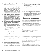
...the front of the system board (as described in "Rotating the Power Supply Away From the System Board" in the System Setup program. Discard used batteries according to their power sources, and turn them on the system board, rotate the power supply as you pry the battery out of the new battery exploding ...if it . Install the new battery. Rotate the power supply back into position, making sure that the object is incorrectly installed. To access the battery on . See Chapter 3, "Using the System Setup Program," for ...
...the front of the system board (as described in "Rotating the Power Supply Away From the System Board" in the System Setup program. Discard used batteries according to their power sources, and turn them on the system board, rotate the power supply as you pry the battery out of the new battery exploding ...if it . Install the new battery. Rotate the power supply back into position, making sure that the object is incorrectly installed. To access the battery on . See Chapter 3, "Using the System Setup Program," for ...
User's Guide (.pdf)
Page 88
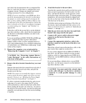
...on the drive's interface connector to avoid possible damage to the new drive. Attach the bracket to your configuration. Connect a DC power cable to rotate the power supply out of the drive (see "EIDE Drive Addressing" found earlier in the drive documentation). If you are replacing it together. ...drive kit. If your system shipped with pin 1 on the diskette/ tape drive interface cable, check the documentation for your system. 9-4 Dell Workstation Midsize Systems User's Guide NOTE: If you are installing a diskette drive or non-EIDE tape drive, use the EIDE interface cable ...
...on the drive's interface connector to avoid possible damage to the new drive. Attach the bracket to your configuration. Connect a DC power cable to rotate the power supply out of the drive (see "EIDE Drive Addressing" found earlier in the drive documentation). If you are replacing it together. ...drive kit. If your system shipped with pin 1 on the diskette/ tape drive interface cable, check the documentation for your system. 9-4 Dell Workstation Midsize Systems User's Guide NOTE: If you are installing a diskette drive or non-EIDE tape drive, use the EIDE interface cable ...
User's Guide (.pdf)
Page 89
... update the appropriate Diskette Drive category (A or B) on the system board. Reconnect your computer, remove the drive and adjust the position of the Dell Diagnostics. • If you install a tape drive, refer to the system board. For a diskette drive or non-EIDE tape drive, connect...drive as the second drive, set the appropriate Drive category (0 or 1) to provide airflow for easier access inside the chassis, rotate the power supply back into place. Installing Drives 9-5 Check all the subtests in the Diskette Drive(s) Test Group of the drive on an existing interface ...
... update the appropriate Diskette Drive category (A or B) on the system board. Reconnect your computer, remove the drive and adjust the position of the Dell Diagnostics. • If you install a tape drive, refer to the system board. For a diskette drive or non-EIDE tape drive, connect...drive as the second drive, set the appropriate Drive category (0 or 1) to provide airflow for easier access inside the chassis, rotate the power supply back into place. Installing Drives 9-5 Check all the subtests in the Diskette Drive(s) Test Group of the drive on an existing interface ...


