
Glossary
Page 1
ACPI - ANSI - asset tag - A copy of the area or room where the system is used to start your system's hard drive(s) on the dictionary. The modules are mounted into a chassis that is located. BMC - BTU - Centimeter(s). 1 The temperature of a program... Information Model describes the management information utilized by an administrator, for the peripheral devices connected to a system, usually by the DMTF. Dell™ Glossary NOTE: For additional information on storage terminology, visit the Storage Networking Industry Association's website at www.snia.org and click...
ACPI - ANSI - asset tag - A copy of the area or room where the system is used to start your system's hard drive(s) on the dictionary. The modules are mounted into a chassis that is located. BMC - BTU - Centimeter(s). 1 The temperature of a program... Information Model describes the management information utilized by an administrator, for the peripheral devices connected to a system, usually by the DMTF. Dell™ Glossary NOTE: For additional information on storage terminology, visit the Storage Networking Industry Association's website at www.snia.org and click...

Glossary
Page 3
... card. Input/output. IDE - A standard interface between the system's bus and the peripheral device, typically a storage device. Integrated Dell Remote Access Controller. IPv6 - A type of processors with networked storage devices. Gigabit(s); 1024 megabits or 1,073,741,824 bits....a FAT file system structure. InfiniBand - Internet Protocol. flash memory - InfiniBand offers point-to insert or install a device, typically a hard drive or an internal cooling fan, into the host system while the system is an output device. F - However, when referring to 1,...
... card. Input/output. IDE - A standard interface between the system's bus and the peripheral device, typically a storage device. Integrated Dell Remote Access Controller. IPv6 - A type of processors with networked storage devices. Gigabit(s); 1024 megabits or 1,073,741,824 bits....a FAT file system structure. InfiniBand - Internet Protocol. flash memory - InfiniBand offers point-to insert or install a device, typically a hard drive or an internal cooling fan, into the host system while the system is an output device. F - However, when referring to 1,...

Glossary
Page 5
... file that connects to the system board. Your system's unique hardware number on a network. Mb - However, when referring to hard-drive capacity, the term is any system that stores basic system data. A specific location, usually expressed as integrated memory (ROM and ...A system can contain several different forms of the data. memory key - MHz - mirroring - Mirroring functionality is monitored and managed using Dell OpenManage™ Server Administrator. See also striping and RAID. mm - Millimeter(s). MOF - NAS systems have their own operating systems, integrated...
... file that connects to the system board. Your system's unique hardware number on a network. Mb - However, when referring to hard-drive capacity, the term is any system that stores basic system data. A specific location, usually expressed as integrated memory (ROM and ...A system can contain several different forms of the data. memory key - MHz - mirroring - Mirroring functionality is monitored and managed using Dell OpenManage™ Server Administrator. See also striping and RAID. mm - Millimeter(s). MOF - NAS systems have their own operating systems, integrated...

Glossary
Page 6
... across by the number of booting a system via a LAN (without a hard drive or bootable diskette). A video resolution, such as 640 x 480, is used for processor. OID - Each partition can divide a hard drive into multiple physical sections called partitions with the format command. processor - provider ...and columns to signal the processor about hardware errors. A way of pixels up and down. In RAID arrays, a striped hard drive containing parity data. Power distribution unit. Object identifier is associated with managed objects and accesses data and event notifications from a ...
... across by the number of booting a system via a LAN (without a hard drive or bootable diskette). A video resolution, such as 640 x 480, is used for processor. OID - Each partition can divide a hard drive into multiple physical sections called partitions with the format command. processor - provider ...and columns to signal the processor about hardware errors. A way of pixels up and down. In RAID arrays, a striped hard drive containing parity data. Power distribution unit. Object identifier is associated with managed objects and accesses data and event notifications from a ...

Glossary
Page 7
...your system's boot routine and the POST. Examples of providing data redundancy. SCSI - Self-Monitoring Analysis and Reporting Technology. Allows hard drives to report errors and failures to the system. read -only file is one bit at a time and is lost when ...ROM include the program that contains information supplementing or updating the product's documentation. A network architecture that transfers data one that you call Dell for program instructions and data. SAS - Second(s). An I /O port with a 9-pin connector that enables remote networkattached storage devices to...
...your system's boot routine and the POST. Examples of providing data redundancy. SCSI - Self-Monitoring Analysis and Reporting Technology. Allows hard drives to report errors and failures to the system. read -only file is one bit at a time and is lost when ...ROM include the program that contains information supplementing or updating the product's documentation. A network architecture that transfers data one that you call Dell for program instructions and data. SAS - Second(s). An I /O port with a 9-pin connector that enables remote networkattached storage devices to...

Getting Started Guide
Page 11
Memory Architecture Memory module sockets Memory module capacities Minimum RAM Maximum RAM Drives Hard drives Optical drive Connectors Back NIC Serial USB Video Front Video USB Internal USB Video Video type Video memory 1066 or 1333 MHz DDR3 registered or unbuffered Error ... per processor) 64 GB (8 GB dual- and quad-rank DIMMs) Up to twelve 3.5-inch or 2.5-inch, hot-swappable SAS, SATA, or SSD drives and up to two cabled 2.5-inch SAS drives External USB DVD-ROM Two RJ-45 (for integrated 1 GB NICs) 9-pin, DTE, 16550-compatible Two 4-pin, USB 2.0-compliant 15-pin...
Memory Architecture Memory module sockets Memory module capacities Minimum RAM Maximum RAM Drives Hard drives Optical drive Connectors Back NIC Serial USB Video Front Video USB Internal USB Video Video type Video memory 1066 or 1333 MHz DDR3 registered or unbuffered Error ... per processor) 64 GB (8 GB dual- and quad-rank DIMMs) Up to twelve 3.5-inch or 2.5-inch, hot-swappable SAS, SATA, or SSD drives and up to two cabled 2.5-inch SAS drives External USB DVD-ROM Two RJ-45 (for integrated 1 GB NICs) 9-pin, DTE, 16550-compatible Two 4-pin, USB 2.0-compliant 15-pin...

Hardware Owner's Manual
Page 3
Contents 1 About Your System 11 Accessing System Features During Startup 11 Front-Panel Features and Indicators 12 Hard-Drive Indicator Patterns 14 Back-Panel Features and Indicators 15 Guidelines for Connecting Optional External Devices 17 NIC Indicator Codes 18 Power Indicator Codes 18 Diagnostic Lights 20 System Messages 22 Warning Messages 38 Diagnostics Messages 38 Alert Messages 38 Other Information You May Need 39 2 Using the System Setup Program and UEFI Boot Manager 41 Choosing the System Boot Mode 41 Contents 3
Contents 1 About Your System 11 Accessing System Features During Startup 11 Front-Panel Features and Indicators 12 Hard-Drive Indicator Patterns 14 Back-Panel Features and Indicators 15 Guidelines for Connecting Optional External Devices 17 NIC Indicator Codes 18 Power Indicator Codes 18 Diagnostic Lights 20 System Messages 22 Warning Messages 38 Diagnostics Messages 38 Alert Messages 38 Other Information You May Need 39 2 Using the System Setup Program and UEFI Boot Manager 41 Choosing the System Boot Mode 41 Contents 3

Hardware Owner's Manual
Page 5
... Cooling Shroud 69 Hard Drives 69 Removing a Hard-Drive Blank 69 Installing a Hard-Drive Blank 70 Removing a Hot-Swap Hard Drive 70 Installing a Hot-Swap Hard Drive 71 Removing a Hard Drive From a Hard-Drive Carrier 72 Installing a Hard Drive Into a Hard-Drive Carrier 73 Internal Hard Drives 73 Removing an Internal Hard Drive Bay 73 Installing an Internal Hard Drive Bay 75 Removing an Internal Hard Drive From the Internal Hard-Drive Bay 76 Installing a Hard Drive Into a Hard-Drive Bay . . . 76...
... Cooling Shroud 69 Hard Drives 69 Removing a Hard-Drive Blank 69 Installing a Hard-Drive Blank 70 Removing a Hot-Swap Hard Drive 70 Installing a Hot-Swap Hard Drive 71 Removing a Hard Drive From a Hard-Drive Carrier 72 Installing a Hard Drive Into a Hard-Drive Carrier 73 Internal Hard Drives 73 Removing an Internal Hard Drive Bay 73 Installing an Internal Hard Drive Bay 75 Removing an Internal Hard Drive From the Internal Hard-Drive Bay 76 Installing a Hard Drive Into a Hard-Drive Bay . . . 76...

Hardware Owner's Manual
Page 8
... Troubleshooting Power Supplies 135 Troubleshooting System Cooling Problems 136 Troubleshooting a Fan 136 Troubleshooting System Memory 137 Troubleshooting an Internal USB Key 139 Troubleshooting a Hard Drive 140 Troubleshooting an Internal Hard Drive 141 Troubleshooting a Storage Controller 142 Troubleshooting Expansion Cards 143 Troubleshooting Processors 145 5 Running the System Diagnostics 147 Using Online Diagnostics 147 Embedded System...
... Troubleshooting Power Supplies 135 Troubleshooting System Cooling Problems 136 Troubleshooting a Fan 136 Troubleshooting System Memory 137 Troubleshooting an Internal USB Key 139 Troubleshooting a Hard Drive 140 Troubleshooting an Internal Hard Drive 141 Troubleshooting a Storage Controller 142 Troubleshooting Expansion Cards 143 Troubleshooting Processors 145 5 Running the System Diagnostics 147 Using Online Diagnostics 147 Embedded System...

Hardware Owner's Manual
Page 13
Item Indicator, Button, Icon or Connector 2 Power-on indicator/ power button 3 NMI button 4 System identification button 5 Hard drives Description The power-on indicator lights when the system power is not accessible. NOTE: On ACPI-compliant operating systems, turning off . When one of these ... be pressed using the power button causes the system to perform a graceful shutdown before power to twelve 3.5-inch or 2.5-inch, hot-swappable SAS or SATA drives. Used to locate a particular system within a rack. About Your System 13
Item Indicator, Button, Icon or Connector 2 Power-on indicator/ power button 3 NMI button 4 System identification button 5 Hard drives Description The power-on indicator lights when the system power is not accessible. NOTE: On ACPI-compliant operating systems, turning off . When one of these ... be pressed using the power button causes the system to perform a graceful shutdown before power to twelve 3.5-inch or 2.5-inch, hot-swappable SAS or SATA drives. Used to locate a particular system within a rack. About Your System 13

Hardware Owner's Manual
Page 15
Drives are initialized after system power is applied. Drive predicted failure About Your System 15 Hard-Drive Indicators 1 2 1 hard-drive activity indicator (green) 2 hard-drive status indicator (green and amber) Drive-Status Indicator Pattern Blinks green two times per second Off Blinks green, amber, and off Condition Identify drive/preparing for removal Drive ready for insertion or removal NOTE: The drive status indicator remains off until all hard drives are not ready for insertion or removal during this time. Hard-Drive Indicator Patterns Figure 1-2.
Drives are initialized after system power is applied. Drive predicted failure About Your System 15 Hard-Drive Indicators 1 2 1 hard-drive activity indicator (green) 2 hard-drive status indicator (green and amber) Drive-Status Indicator Pattern Blinks green two times per second Off Blinks green, amber, and off Condition Identify drive/preparing for removal Drive ready for insertion or removal NOTE: The drive status indicator remains off until all hard drives are not ready for insertion or removal during this time. Hard-Drive Indicator Patterns Figure 1-2.

Hardware Owner's Manual
Page 22
.... See "Contacting Dell" on page 157. Other failure. Possible system board resource and/or system board hardware failure. See "Troubleshooting System Memory" on page 137. Memory" on page 137. Corrective Action Ensure that the optical drive, and hard drives are properly connected.... See "Troubleshooting a USB Device" on the drives installed in your system. See "Hard Drives" on page 69 for the appropriate drive installed in your system. Memory configuration See "...
.... See "Contacting Dell" on page 157. Other failure. Possible system board resource and/or system board hardware failure. See "Troubleshooting System Memory" on page 137. Memory" on page 137. Corrective Action Ensure that the optical drive, and hard drives are properly connected.... See "Troubleshooting a USB Device" on the drives installed in your system. See "Hard Drives" on page 69 for the appropriate drive installed in your system. Memory configuration See "...
Hardware Owner's Manual
Page 31
...USB Device" on page 130, "Troubleshooting an Internal USB Key" on page 139, and "Troubleshooting a Hard Drive" on page 157. Use a bootable USB key, optical drive, or hard drive. No timer tick interrupt. If the problem persists, see "Getting Help" on page 140. See "... Setup Program and UEFI Boot Manager" on Incorrect configuration hard drive. No boot sector on page 41. Check the hard drive configuration settings in the Link Width is y. See your hard drive. Faulty or missing optical drive subsystem, hard drive, or hard drive subsystem, or no operating system on...
...USB Device" on page 130, "Troubleshooting an Internal USB Key" on page 139, and "Troubleshooting a Hard Drive" on page 157. Use a bootable USB key, optical drive, or hard drive. No timer tick interrupt. If the problem persists, see "Getting Help" on page 140. See "... Setup Program and UEFI Boot Manager" on Incorrect configuration hard drive. No boot sector on page 41. Check the hard drive configuration settings in the Link Width is y. See your hard drive. Faulty or missing optical drive subsystem, hard drive, or hard drive subsystem, or no operating system on...

Hardware Owner's Manual
Page 32
... the system. See "General Memory Module Installation Guidelines" on page 143. Read fault. defective. See Figure 6-1 for the appropriate drive(s) installed in your system. Install the NVRAM_CLR jumper in initializing PCIe device; If the problem persists, see "Troubleshooting Expansion Cards" ...Replace the optical medium, read from the hard drive, USB medium, or USB optical drive, or USB device, device. See "Troubleshooting a USB Device" on page 130 or "Troubleshooting a Hard Drive" on the disk, cables, or optical drive cables or the requested sector is no device...
... the system. See "General Memory Module Installation Guidelines" on page 143. Read fault. defective. See Figure 6-1 for the appropriate drive(s) installed in your system. Install the NVRAM_CLR jumper in initializing PCIe device; If the problem persists, see "Troubleshooting Expansion Cards" ...Replace the optical medium, read from the hard drive, USB medium, or USB optical drive, or USB device, device. See "Troubleshooting a USB Device" on page 130 or "Troubleshooting a Hard Drive" on the disk, cables, or optical drive cables or the requested sector is no device...

Hardware Owner's Manual
Page 33
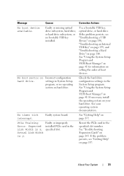
Message Causes Sector not found. Faulty hard drive, USB Seek error. Shutdown failure. See "Getting Help" on page 82. See "System Memory" on page 157. The BIOS setting has been disabled. Corrective Actions ... replace the faulty memory module. About Your System 33 Seek operation failed. module may be ignored. See "Troubleshooting a USB Device" on page 130 or "Troubleshooting a Hard Drive" on page 137. Reconfigure the memory modules for the appropriate...
Message Causes Sector not found. Faulty hard drive, USB Seek error. Shutdown failure. See "Getting Help" on page 82. See "System Memory" on page 157. The BIOS setting has been disabled. Corrective Actions ... replace the faulty memory module. About Your System 33 Seek operation failed. module may be ignored. See "Troubleshooting a USB Device" on page 130 or "Troubleshooting a Hard Drive" on page 137. Reconfigure the memory modules for the appropriate...

Hardware Owner's Manual
Page 39
.... Replace the USB medium or device. See "Troubleshooting a USB Device" on page 130, "Troubleshooting an Internal USB Key" on page 139, and "Troubleshooting a Hard Drive" on page 148 for drive, temperature, fan, and power conditions. Alert messages include information, status, warning, and failure messages for more information about system diagnostics. Message Causes Corrective... full name of an abbreviation or acronym used in this table, see the systems management software documentation. For more information, see the Glossary at support.dell.com.
.... Replace the USB medium or device. See "Troubleshooting a USB Device" on page 130, "Troubleshooting an Internal USB Key" on page 139, and "Troubleshooting a Hard Drive" on page 148 for drive, temperature, fan, and power conditions. Alert messages include information, status, warning, and failure messages for more information about system diagnostics. Message Causes Corrective... full name of an abbreviation or acronym used in this table, see the systems management software documentation. For more information, see the Glossary at support.dell.com.

Hardware Owner's Manual
Page 48
Auto automatically chooses an emulation type. Options are Enabled, Enabled with PXE, and Enabled with PXE; PXE support allows the system to boot from hard drives in which the BIOS attempts to boot from the network. Other NICs: Enabled) Enables or disables the embedded NICs. MAC Address Displays the MAC address ... NICx (NIC1 default: Enabled with iSCSI Boot. If this field is enabled and the system has failed to boot, the system reattempts to act as a hard drive. User Accessible USB Ports (All Ports On default) Enables or disables the user-accessible USB ports.
Auto automatically chooses an emulation type. Options are Enabled, Enabled with PXE, and Enabled with PXE; PXE support allows the system to boot from hard drives in which the BIOS attempts to boot from the network. Other NICs: Enabled) Enables or disables the embedded NICs. MAC Address Displays the MAC address ... NICx (NIC1 default: Enabled with iSCSI Boot. If this field is enabled and the system has failed to boot, the system reattempts to act as a hard drive. User Accessible USB Ports (All Ports On default) Enables or disables the user-accessible USB ports.

Hardware Owner's Manual
Page 64
Inside the System 5 4 3 2 1 6 10 1 cooling fan 3 expansion-card riser 5 cooling shroud 7 memory modules (8) 9 SAS backplane 7 8 9 2 internal hard drives (2) 4 power supply bays (2) 6 heat sink/processor (2) 8 system cooling fans (4) 10 hard drives (12) 64 Installing System Components Figure 3-1.
Inside the System 5 4 3 2 1 6 10 1 cooling fan 3 expansion-card riser 5 cooling shroud 7 memory modules (8) 9 SAS backplane 7 8 9 2 internal hard drives (2) 4 power supply bays (2) 6 heat sink/processor (2) 8 system cooling fans (4) 10 hard drives (12) 64 Installing System Components Figure 3-1.

Hardware Owner's Manual
Page 69
... directed by Dell is free of the numbered fan bays as a guide. 2 Press the cooling shroud down into the chassis. 3 Close the system. Installing the Cooling Shroud CAUTION: Many repairs may only be configured as hotswappable. See "Removing the Front Bezel" on page 65. 2 Grasp the front of the hard-drive blank, press...
... directed by Dell is free of the numbered fan bays as a guide. 2 Press the cooling shroud down into the chassis. 3 Close the system. Installing the Cooling Shroud CAUTION: Many repairs may only be configured as hotswappable. See "Removing the Front Bezel" on page 65. 2 Grasp the front of the hard-drive blank, press...

Hardware Owner's Manual
Page 70
... the hard drive out of the drive bay. 5 Insert a drive blank in the vacated drive bay. When the drive indicators are off, the drive is powered down. See "Hard-Drive Indicator Patterns" on page 70. Removing and Installing a Hard-Drive Blank 1 2 1 hard-drive blank 2 release lever Installing a Hard-Drive Blank Align the hard-drive blank with the drive bay and insert the blank into the drive bay until the hard-drive...
... the hard drive out of the drive bay. 5 Insert a drive blank in the vacated drive bay. When the drive indicators are off, the drive is powered down. See "Hard-Drive Indicator Patterns" on page 70. Removing and Installing a Hard-Drive Blank 1 2 1 hard-drive blank 2 release lever Installing a Hard-Drive Blank Align the hard-drive blank with the drive bay and insert the blank into the drive bay until the hard-drive...


