Glossary
Page 4
... Land grid array. m - Milliampere(s). 4 jumper - Kilobit(s) per second. Local area network. See also bus. LOM - LVD - mA - A protocol that lights up when a current is usually confined to the same building or a few nearby buildings, with all equipment linked by an IRQ line to a switch that...KVM - LGA - On a system with two or more pins emerging from which the keyboard and mouse are used. KB - Keyboard/video/mouse. Light-emitting diode. iSCSI - A LAN is passed through it. Meter(s). A signal that allows selection of changing the circuitry in a board. An ...
... Land grid array. m - Milliampere(s). 4 jumper - Kilobit(s) per second. Local area network. See also bus. LOM - LVD - mA - A protocol that lights up when a current is usually confined to the same building or a few nearby buildings, with all equipment linked by an IRQ line to a switch that...KVM - LGA - On a system with two or more pins emerging from which the keyboard and mouse are used. KB - Keyboard/video/mouse. Light-emitting diode. iSCSI - A LAN is passed through it. Meter(s). A signal that allows selection of changing the circuitry in a board. An ...
Glossary
Page 45
Internet Protocol IPv6 - Kilo 1000 Kb - Kilobits per second kg - Liquid crystal display LED - Light-emitting diode LGA - Land Grid Array LOM - Keyboard/video/mouse KVM LAN - Meter mA - Kilobyte 1 KB = 1024 Kbps - Kilobytes per second KBps - Kilohertz KVM - LAN ...
Internet Protocol IPv6 - Kilo 1000 Kb - Kilobits per second kg - Liquid crystal display LED - Light-emitting diode LGA - Land Grid Array LOM - Keyboard/video/mouse KVM LAN - Meter mA - Kilobyte 1 KB = 1024 Kbps - Kilobytes per second KBps - Kilohertz KVM - LAN ...
CLI Guide
Page 201
... The IP address of the node that support this parameter to be written. To turn on the Service Action Allowed indicator light, set this parameter are listed in the Syntax Element Statement Data table that follows. To turn on . FFFF). serviceAllowedIndicator The...to off the remote login feature, set this parameter to the network. rloginEnabled The setting for whether the Service Action Allowed indicator light is turned on or turned off . Parameter Description ethernetPort The attributes (options) for the IPv6 router is (0-FFFF):(0-FFFF):(0-FFFF...
... The IP address of the node that support this parameter to be written. To turn on the Service Action Allowed indicator light, set this parameter are listed in the Syntax Element Statement Data table that follows. To turn on . FFFF). serviceAllowedIndicator The...to off the remote login feature, set this parameter to the network. rloginEnabled The setting for whether the Service Action Allowed indicator light is turned on or turned off . Parameter Description ethernetPort The attributes (options) for the IPv6 router is (0-FFFF):(0-FFFF):(0-FFFF...
CLI Guide
Page 251
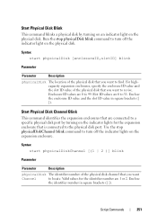
...want Channel to the physical disk port. Slot ID values are connected to a specific physical disk port by turning on an indicator light on the physical disk. Start Physical Disk Blink This command blinks a physical disk by turning on the expansion enclosure. Script Commands 251...to 31. Valid values for the expansion enclosure that you want to turn off the indicator lights on the indicator lights for the identifier number are 0 to turn off the indicator light on the physical disk. Start Physical Disk Channel Blink This command identifies the expansion enclosures ...
...want Channel to the physical disk port. Slot ID values are connected to a specific physical disk port by turning on an indicator light on the physical disk. Start Physical Disk Blink This command blinks a physical disk by turning on the expansion enclosure. Script Commands 251...to 31. Valid values for the expansion enclosure that you want to turn off the indicator lights on the indicator lights for the identifier number are 0 to turn off the indicator light on the physical disk. Start Physical Disk Channel Blink This command identifies the expansion enclosures ...
CLI Guide
Page 257
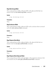
Stop Physical Disk Blink This command turns off the indicator light on the physical disk that was turned on by the start physicalDisk blink command. Stop Enclosure Blink This command turns off the indicator LED on ...the enclosure that was turned on by the start enclosure blink command. Stop Physical Disk Channel Blink This command turns off the indicator lights on the expansion enclosures that were turned on by the start diskGroup blink command. Script Commands 257 Syntax stop enclosure blink Parameters None. Syntax stop...
Stop Physical Disk Blink This command turns off the indicator light on the physical disk that was turned on by the start physicalDisk blink command. Stop Enclosure Blink This command turns off the indicator LED on ...the enclosure that was turned on by the start enclosure blink command. Stop Physical Disk Channel Blink This command turns off the indicator lights on the expansion enclosures that were turned on by the start diskGroup blink command. Script Commands 257 Syntax stop enclosure blink Parameters None. Syntax stop...
CLI Guide
Page 259
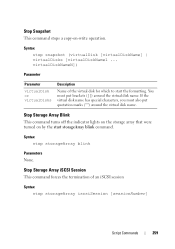
... virtualDisk or virtualDisks Description Name of an iSCSI session Syntax stop storageArray blink Parameters None. Stop Storage Array Blink This command turns off the indicator lights on the storage array that were turned on -write operation. Syntax stop snapshot (virtualDisk [virtualDiskName] | virtualDisks [virtualDiskName1 ... Stop Snapshot This command stops a copy-on by...
... virtualDisk or virtualDisks Description Name of an iSCSI session Syntax stop storageArray blink Parameters None. Stop Storage Array Blink This command turns off the indicator lights on the storage array that were turned on -write operation. Syntax stop snapshot (virtualDisk [virtualDiskName] | virtualDisks [virtualDiskName1 ... Stop Snapshot This command stops a copy-on by...
Owner's Manual
Page 25
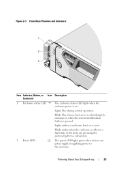
...amber when the enclosure is either in a fault state or the hosts are not using the preferred path to the enclosure. The power LED lights green when at least one power supply is pressed. Planning: About Your Storage Array 25 Front-Bezel Features and Indicators 1 2 3 Item Indicator..., Button, or Icon Connector 1 Enclosure status LED 2 Power LED Description The enclosure status LED lights when the enclosure power is reset. Lights amber as enclosure boots or is on. Blinks blue when a host server is identifying the enclosure or when the system identification...
...amber when the enclosure is either in a fault state or the hosts are not using the preferred path to the enclosure. The power LED lights green when at least one power supply is pressed. Planning: About Your Storage Array 25 Front-Bezel Features and Indicators 1 2 3 Item Indicator..., Button, or Icon Connector 1 Enclosure status LED 2 Power LED Description The enclosure status LED lights when the enclosure power is reset. Lights amber as enclosure boots or is on. Blinks blue when a host server is identifying the enclosure or when the system identification...
Owner's Manual
Page 30
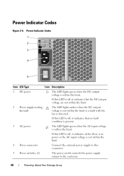
...Codes 1 2 3 4 5 Item LED Type Icon Description 1 DC power The LED lights green when the DC output voltage is within the limit or a fault with the fan... it indicates that the DC output voltage are not within the limit. 2 Power supply/cooling fan fault The LED lights amber when the DC output voltage is detected. If this LED is off , it indicates either there is no ...fault condition is present. 3 AC power The LED lights green when the AC input voltage is not within the limit. Power Indicator Codes Figure 2-6. If this LED is ...
...Codes 1 2 3 4 5 Item LED Type Icon Description 1 DC power The LED lights green when the DC output voltage is within the limit or a fault with the fan... it indicates that the DC output voltage are not within the limit. 2 Power supply/cooling fan fault The LED lights amber when the DC output voltage is detected. If this LED is off , it indicates either there is no ...fault condition is present. 3 AC power The LED lights green when the AC input voltage is not within the limit. Power Indicator Codes Figure 2-6. If this LED is ...
Owner's Manual
Page 33
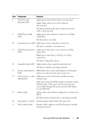
... switch Activating this LED changes to three links are connected. Off when battery backup unit is down. 12 Controller fault LED Lights amber when controller fault detected. Lights amber when one to indicate Cache Offload status. Blinks green when there is pressed. 14 Cache active or cache...controller memory offload LED contains data. Off when controller is not turned on. 11 iSCSI IN port activity Lights green when there is no link. 10 Controller power LED Lights green when controller is turned on 1Gbps LED connection. LED button on enclosure front panel is Activity on...
... switch Activating this LED changes to three links are connected. Off when battery backup unit is down. 12 Controller fault LED Lights amber when controller fault detected. Lights amber when one to indicate Cache Offload status. Blinks green when there is pressed. 14 Cache active or cache...controller memory offload LED contains data. Off when controller is not turned on. 11 iSCSI IN port activity Lights green when there is no link. 10 Controller power LED Lights green when controller is turned on 1Gbps LED connection. LED button on enclosure front panel is Activity on...
Owner's Manual
Page 34
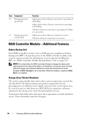
Item Component 18 Management port speed LED 19 Management port activity LED Function Lights green when ethernet connection is operating at which shutdown occurs. Lights green when ethernet connection is not active. Off when ethernet connection is active. For information on removing and installing the BBU, ...data cache setting based on page 210. When the battery is replaced, Write Back is operating at 100 Mbps. It is not active. Lights amber when ethernet connection is operating at 10 Mbps or is not necessary to non-volatile memory in the event of a power outage. ...
Item Component 18 Management port speed LED 19 Management port activity LED Function Lights green when ethernet connection is operating at which shutdown occurs. Lights green when ethernet connection is not active. Off when ethernet connection is active. For information on removing and installing the BBU, ...data cache setting based on page 210. When the battery is replaced, Write Back is operating at 100 Mbps. It is not active. Lights amber when ethernet connection is operating at 10 Mbps or is not necessary to non-volatile memory in the event of a power outage. ...
Owner's Manual
Page 232
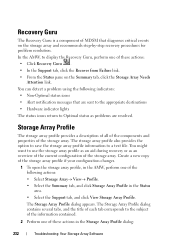
... configuration changes. 1 To open the storage array profile, in the AMW, perform one of MDSM that are sent to the appropriate destinations • Hardware indicator lights The status icons return to a text file.
... configuration changes. 1 To open the storage array profile, in the AMW, perform one of MDSM that are sent to the appropriate destinations • Hardware indicator lights The status icons return to a text file.
Deployment Guide
Page 24
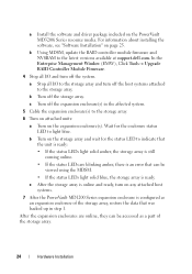
...array. 24 Hardware Installation For information about installing the software, see "Software Installation" on any attached host systems. 7 After the PowerVault MD1200 Series expansion enclosure is online and ready, turn off the expansion enclosure(s) in the affected system. 5 Cable the expansion enclosure...the status LEDs light solid blue, the storage array is an error that was backed up in step 1. b Turn off the host systems attached to the latest versions available at support.dell.com. a Install the software and driver package included on the PowerVault MD3200i Series resource media...
...array. 24 Hardware Installation For information about installing the software, see "Software Installation" on any attached host systems. 7 After the PowerVault MD1200 Series expansion enclosure is online and ready, turn off the expansion enclosure(s) in the affected system. 5 Cable the expansion enclosure...the status LEDs light solid blue, the storage array is an error that was backed up in step 1. b Turn off the host systems attached to the latest versions available at support.dell.com. a Install the software and driver package included on the PowerVault MD3200i Series resource media...
Deployment Guide
Page 25
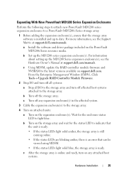
... controller module firmware and NVSRAM to the latest versions available on the PowerVault MD3200i Series resource media. a Install the software and driver package included on support.dell.com. c Turn off the storage array. From the Enterprise Management Window...dell.com/manuals. Expanding With New PowerVault MD1200 Series Expansion Enclosures Perform the following steps to attach new PowerVault MD1200 series expansion enclosures to a PowerVault MD3200i Series storage array: 1 Before adding the expansion enclosure(s), ensure that can be viewed using MDSM. • If the status LEDs light...
... controller module firmware and NVSRAM to the latest versions available on the PowerVault MD3200i Series resource media. a Install the software and driver package included on support.dell.com. c Turn off the storage array. From the Enterprise Management Window...dell.com/manuals. Expanding With New PowerVault MD1200 Series Expansion Enclosures Perform the following steps to attach new PowerVault MD1200 series expansion enclosures to a PowerVault MD3200i Series storage array: 1 Before adding the expansion enclosure(s), ensure that can be viewed using MDSM. • If the status LEDs light...


