
Service Manual
Page 5
...iii PowerVault 130T Service Manual Contents Preface About This Manual Organization Alert Messages Related Publications Ordering Publications Safety and ESD Safety Lifting Techniques Using Shoulders, Elbows, Wrists, and Hands Preventing Electrostatic Discharge Damage Precautions ESD-Protection Procedure Rack-Mounted Library Safety and Precautions Chapter 1. General Information Components Component Locations Robot Electronics Module Operator Panel Cartridge Access Port Interfaces Storage Cells Removable Five-Cell Magazine Software Microcode DLT Drives Chapter...
...iii PowerVault 130T Service Manual Contents Preface About This Manual Organization Alert Messages Related Publications Ordering Publications Safety and ESD Safety Lifting Techniques Using Shoulders, Elbows, Wrists, and Hands Preventing Electrostatic Discharge Damage Precautions ESD-Protection Procedure Rack-Mounted Library Safety and Precautions Chapter 1. General Information Components Component Locations Robot Electronics Module Operator Panel Cartridge Access Port Interfaces Storage Cells Removable Five-Cell Magazine Software Microcode DLT Drives Chapter...
Service Manual
Page 6
PowerVault 130T Service Manual Loading Microcode Setting Tape Drive SCSI IDs Setting the Library SCSI ID Cleaning Tape Drives 2-10 2-12 2-13 2-14 Chapter 3. Removal and Replacement Preparation Powering On and Off the Library Removing the Front Door Required Tools Customer Replaceable Units Field Replaceable Units CYC Card CYO Card DLT Drive Tray Assembly Electronics Module Hand/Camera Assembly Theta Motor Z Motor Check-Out Procedures 3-1 3-1 3-2 3-3 3-4 3-4 3-4 3-6 3-8 3-13 3-19 3-25 3-32 3-38 3-43 Appendix A. Supporting Information A-1 Specifications A-1 ...
PowerVault 130T Service Manual Loading Microcode Setting Tape Drive SCSI IDs Setting the Library SCSI ID Cleaning Tape Drives 2-10 2-12 2-13 2-14 Chapter 3. Removal and Replacement Preparation Powering On and Off the Library Removing the Front Door Required Tools Customer Replaceable Units Field Replaceable Units CYC Card CYO Card DLT Drive Tray Assembly Electronics Module Hand/Camera Assembly Theta Motor Z Motor Check-Out Procedures 3-1 3-1 3-2 3-3 3-4 3-4 3-4 3-6 3-8 3-13 3-19 3-25 3-32 3-38 3-43 Appendix A. Supporting Information A-1 Specifications A-1 ...
Service Manual
Page 9
... access doors and power-on and power-off the library. Appendix A "Supporting Information" provides library and drive specifications. PowerVault 130T Service Manual Preface About This Manual About This Manual This manual provides instructions for the technically trained personnel in charge of those operations. It is organized as follows: Chapter 1 "General Information" provides a high-level description of customer data or application software, or long-term health hazard to rules or procedures...
... access doors and power-on and power-off the library. Appendix A "Supporting Information" provides library and drive specifications. PowerVault 130T Service Manual Preface About This Manual About This Manual This manual provides instructions for the technically trained personnel in charge of those operations. It is organized as follows: Chapter 1 "General Information" provides a high-level description of customer data or application software, or long-term health hazard to rules or procedures...
Service Manual
Page 15
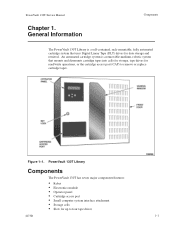
... interface attachment Storage cells Slots for read/write operations, or the cartridge access port (CAP) to four tape drives 4473D 1-1 Figure 1-1. An automated cartridge system is a self-contained, rack-mountable, fully automated cartridge system that mounts and dismounts cartridge tapes into cells for storage, tape drives for up to remove or replace cartridge tapes. PowerVault 130T Service Manual Chapter 1. General Information Components The PowerVault 130T Library is a removable-medium, robotic system that uses Digital Linear Tape (DLT) drives for data storage...
... interface attachment Storage cells Slots for read/write operations, or the cartridge access port (CAP) to four tape drives 4473D 1-1 Figure 1-1. An automated cartridge system is a self-contained, rack-mountable, fully automated cartridge system that mounts and dismounts cartridge tapes into cells for storage, tape drives for up to remove or replace cartridge tapes. PowerVault 130T Service Manual Chapter 1. General Information Components The PowerVault 130T Library is a removable-medium, robotic system that uses Digital Linear Tape (DLT) drives for data storage...
Service Manual
Page 18
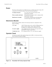
... host system (auto ranging) provides AC power to tape drives for the library For cooling the library, CYC card, and power supply Operator Panel The operator panel has three light emitting diodes (LEDs), five function buttons, and a four-line 20-character display. PowerVault 130T Library Operator Panel 1-4 4473D Component Locations PowerVault 130T Service Manual Robot The robot is the mechanical assembly that moves cartridge tapes from the storage cells, CAP, or tape drives Electronics Module The electronics module...
... host system (auto ranging) provides AC power to tape drives for the library For cooling the library, CYC card, and power supply Operator Panel The operator panel has three light emitting diodes (LEDs), five function buttons, and a four-line 20-character display. PowerVault 130T Library Operator Panel 1-4 4473D Component Locations PowerVault 130T Service Manual Robot The robot is the mechanical assembly that moves cartridge tapes from the storage cells, CAP, or tape drives Electronics Module The electronics module...
Service Manual
Page 19
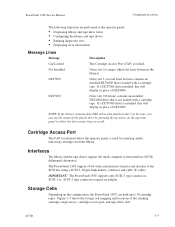
... configuration, the PowerVault 130T can see the status of DLT4000. NOTE: If the library contains four DLT drives (the fourth in place of the fourth drive by pressing the up to the SCSI bus using a SCSI-3, 68-pin, high density connector and cable (P-cable). If a DLT7000 drive is installed, this will display in slot 3 at the operator panel: Displaying library and tape drive status Configuring the library and tape drives Running diagnostic tests Displaying error...
... configuration, the PowerVault 130T can see the status of DLT4000. NOTE: If the library contains four DLT drives (the fourth in place of the fourth drive by pressing the up to the SCSI bus using a SCSI-3, 68-pin, high density connector and cable (P-cable). If a DLT7000 drive is installed, this will display in slot 3 at the operator panel: Displaying library and tape drive status Configuring the library and tape drives Running diagnostic tests Displaying error...
Service Manual
Page 21
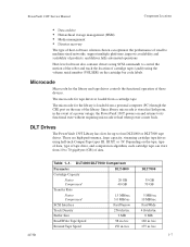
... reload when power comes back. These are high-performance, large capacity, streaming cartridge tape drives using the volume serial number (VOLSER) on the tape, type of data, type of tape drive, and compression algorithm, each cartridge tape can optimize the performance of small to medium-sized networks, support multiple platforms, improve availability and scalability of products, and deliver fully automated operations. PowerVault 130T Service Manual Component Locations Data archive Hierarchical storage management (HSM) Media management Disaster recovery The type of host-software solution...
... reload when power comes back. These are high-performance, large capacity, streaming cartridge tape drives using the volume serial number (VOLSER) on the tape, type of data, type of tape drive, and compression algorithm, each cartridge tape can optimize the performance of small to medium-sized networks, support multiple platforms, improve availability and scalability of products, and deliver fully automated operations. PowerVault 130T Service Manual Component Locations Data archive Hierarchical storage management (HSM) Media management Disaster recovery The type of host-software solution...
Service Manual
Page 25
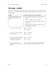
... Procedures diagnostic tests on the operator panel. Do you have a power problem? Yes: Go to TIP 2000 No: Go to Step 2. 2. Problem A failure has been detected, or is suspected with the library or tape drive. 1. There is no FSC is displayed, begin the trouble isolation process here to Step 4. 4. No: Go to help isolate and fix the problem. PowerVault 130T Service Manual TIP 0000: START TIP...
... Procedures diagnostic tests on the operator panel. Do you have a power problem? Yes: Go to TIP 2000 No: Go to Step 2. 2. Problem A failure has been detected, or is suspected with the library or tape drive. 1. There is no FSC is displayed, begin the trouble isolation process here to Step 4. 4. No: Go to help isolate and fix the problem. PowerVault 130T Service Manual TIP 0000: START TIP...
Service Manual
Page 26
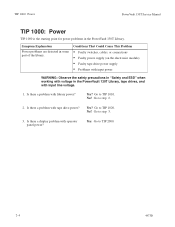
... a problem with operator panel power? Go to TIP 1010. Yes: Go to step 2. 2. Symptom Explanation Power problems are detected in the PowerVault 130T Library. Yes? Is there a display problem with tape drive power? Conditions That Could Cause This Problem Faulty switches, cables, or connections Faulty power supply (on the electronics module) Faulty tape drive power supply Problems with input power WARNING: Observe the safety precautions in "Safety and ESD" when working with voltage in the PowerVault 130T Library, tape drives, and...
... a problem with operator panel power? Go to TIP 1010. Yes: Go to step 2. 2. Symptom Explanation Power problems are detected in the PowerVault 130T Library. Yes? Is there a display problem with tape drive power? Conditions That Could Cause This Problem Faulty switches, cables, or connections Faulty power supply (on the electronics module) Faulty tape drive power supply Problems with input power WARNING: Observe the safety precautions in "Safety and ESD" when working with voltage in the PowerVault 130T Library, tape drives, and...

Service Manual
Page 31
... is required for diagnostics. PowerVault 130T Service Manual Library Diagnostics Library Diagnostics The following diagnostic routines are finished, press MENU (once or several times, as required) to exit, retrieve the diagnostic tape, and return to exit the Maintenance mode. Initialize Mechs Initializes the library and performs an audit. Then follow the prompts displayed on the operator panel. Mount Diagnostic Robot mounts...
... is required for diagnostics. PowerVault 130T Service Manual Library Diagnostics Library Diagnostics The following diagnostic routines are finished, press MENU (once or several times, as required) to exit, retrieve the diagnostic tape, and return to exit the Maintenance mode. Initialize Mechs Initializes the library and performs an audit. Then follow the prompts displayed on the operator panel. Mount Diagnostic Robot mounts...

Service Manual
Page 32
... Operator Panel displays Receiving. The Operator Panel displays Writing..... . 2-10 4473D Important Procedures PowerVault 130T Service Manual Important Procedures This section includes the following procedures that is usually done by typing A: and pressing RETURN 5. Next, the PC displays Send Status: File transfer completed successfully. During boot, while the library display reads Available (visible for the serial port number. The operator panel displays the choices >Functional Reflash NVRAM test & init Select Functional Reflash using...
... Operator Panel displays Receiving. The Operator Panel displays Writing..... . 2-10 4473D Important Procedures PowerVault 130T Service Manual Important Procedures This section includes the following procedures that is usually done by typing A: and pressing RETURN 5. Next, the PC displays Send Status: File transfer completed successfully. During boot, while the library display reads Available (visible for the serial port number. The operator panel displays the choices >Functional Reflash NVRAM test & init Select Functional Reflash using...

Service Manual
Page 33
... Reflash using the arrow buttons and press ENTER The operator panel displays Connect CSE port... 12. PowerVault 130T Service Manual Important Procedures WARNING: Do not power down or reset the library while in the serial port number that is connected to the cable and press ENTER. Type in the writing mode. 6. The PC displays Sending and the library Operator Panel displays Receiving Next, the PC displays Send Status: File transfer completed successfully. The library will reboot...
... Reflash using the arrow buttons and press ENTER The operator panel displays Connect CSE port... 12. PowerVault 130T Service Manual Important Procedures WARNING: Do not power down or reset the library while in the serial port number that is connected to the cable and press ENTER. Type in the writing mode. 6. The PC displays Sending and the library Operator Panel displays Receiving Next, the PC displays Send Status: File transfer completed successfully. The library will reboot...
Service Manual
Page 34
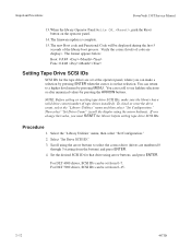
... of tape drives installed). The format appears below: Boot: #.#.## Func: #.#.## Setting Tape Drive SCSI IDs SCSI IDs for that selection. You can scroll to a higher-level menu by pressing the ARROW buttons. When the library Operator Panel Write OK..., push the Reset button on that drive using the arrow buttons). You can return to see hidden selections or alter numerical values by pressing MENU. Important Procedures PowerVault 130T Service Manual...
... of tape drives installed). The format appears below: Boot: #.#.## Func: #.#.## Setting Tape Drive SCSI IDs SCSI IDs for that selection. You can scroll to a higher-level menu by pressing the ARROW buttons. When the library Operator Panel Write OK..., push the Reset button on that drive using the arrow buttons). You can return to see hidden selections or alter numerical values by pressing MENU. Important Procedures PowerVault 130T Service Manual...
Service Manual
Page 37
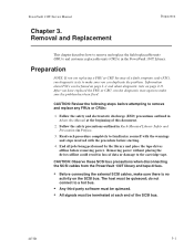
... with the warnings and steps involved with the procedure before starting. 4. CAUTION: Observe these SCSI bus precautions when disconnecting the SCSI cables from the PowerVault 130T library and tape drives. All signals must be found on the SCSI bus. Read each end of data or damage to the cartridge tape. CAUTION: Review the following steps before removing power. Before connecting the external SCSI cables, make sure the problem has been...
... with the warnings and steps involved with the procedure before starting. 4. CAUTION: Observe these SCSI bus precautions when disconnecting the SCSI cables from the PowerVault 130T library and tape drives. All signals must be found on the SCSI bus. Read each end of data or damage to the cartridge tape. CAUTION: Review the following steps before removing power. Before connecting the external SCSI cables, make sure the problem has been...
Service Manual
Page 40
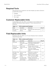
... card Part of the Microprocessor that monitors electronics module and controls all precautions and instructions. DLT Drive Tray Left rear of the Assembly library Holds drive assembly for configuring assembly) CAP. Used for read/write operations 3-13 Electronics module Right rear of 3-6 (EM) the 130T library. Follow all functions of the Houses the power supply, library CYC card, fan assemblies 3-19 Hand/camera assembly Attaches to be removed/replaced only...
... card Part of the Microprocessor that monitors electronics module and controls all precautions and instructions. DLT Drive Tray Left rear of the Assembly library Holds drive assembly for configuring assembly) CAP. Used for read/write operations 3-13 Electronics module Right rear of 3-6 (EM) the 130T library. Follow all functions of the Houses the power supply, library CYC card, fan assemblies 3-19 Hand/camera assembly Attaches to be removed/replaced only...

Service Manual
Page 43
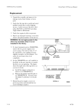
... the View Configuration menu in the PowerVault 130T User's Guide. 4473D 3-7 Install the 18 screws attaching the CYC card to the standoffs on the electronics module chassis. 3. Refer to Figure 3-3 for connector locations. 5. Replace the electronics module following the procedures beginning on page 3-23. 6. Manually log all of the removal procedure above. Reconfigure the new CYC card using a Torx driver with a T-10 bit. Refer to Figure 3-3 for instructions about setting library and tape drive SCSI...
... the View Configuration menu in the PowerVault 130T User's Guide. 4473D 3-7 Install the 18 screws attaching the CYC card to the standoffs on the electronics module chassis. 3. Refer to Figure 3-3 for connector locations. 5. Replace the electronics module following the procedures beginning on page 3-23. 6. Manually log all of the removal procedure above. Reconfigure the new CYC card using a Torx driver with a T-10 bit. Refer to Figure 3-3 for instructions about setting library and tape drive SCSI...
Service Manual
Page 52
... installed in place. 3-16 PowerVault 130T Service Manual 4473D Report any damaged, missing, or incorrect items to the drive tray assembly when it in the library. 5. Labels on top of the tape drive (as shown to set TERMPWR on the invoice. WARNING: Do not apply power to the phone number on . For safety, do not remove the cover completely. 6. Verify that required cables are replacing...
... installed in place. 3-16 PowerVault 130T Service Manual 4473D Report any damaged, missing, or incorrect items to the drive tray assembly when it in the library. 5. Labels on top of the tape drive (as shown to set TERMPWR on the invoice. WARNING: Do not apply power to the phone number on . For safety, do not remove the cover completely. 6. Verify that required cables are replacing...
Service Manual
Page 81
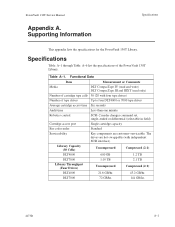
... Robotics control SCSI-2 media changer command set, single-ended or differential (selectable in field) Cartridge access port Single cartridge capacity Bar code reader Standard Serviceability Key components are hot-swappable (with four tape drives) Number of the PowerVault 130T Library. Table A-1. Supporting Information Specifications This appendix lists the specifications for the PowerVault 130T Library. Functional Data Item Measurement or Comments Media DLT CompacTape IV (read and write) DLT CompacTape III and IIIXT (read only) Number of cartridge tape...
... Robotics control SCSI-2 media changer command set, single-ended or differential (selectable in field) Cartridge access port Single cartridge capacity Bar code reader Standard Serviceability Key components are hot-swappable (with four tape drives) Number of the PowerVault 130T Library. Table A-1. Supporting Information Specifications This appendix lists the specifications for the PowerVault 130T Library. Functional Data Item Measurement or Comments Media DLT CompacTape IV (read and write) DLT CompacTape III and IIIXT (read only) Number of cartridge tape...
Service Manual
Page 85
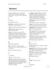
... refer to the glossary in a transport. CYC card. The spine of an library, listing the panel types and drives. CYO card. disabled (1) Inactive. (2) Off. E enabled (1) Active. (2) On. Magnetic tape enclosed in a library by library number, VOLSER, panel, row, and column. cell Storage location for transferring data between the CYC card and reach mechanism; configuration. Operator panel interface. byte An 8-bit binary character. cartridge access port (CAP). audit (1) For a library, a part...
... refer to the glossary in a transport. CYC card. The spine of an library, listing the panel types and drives. CYO card. disabled (1) Inactive. (2) Off. E enabled (1) Active. (2) On. Magnetic tape enclosed in a library by library number, VOLSER, panel, row, and column. cell Storage location for transferring data between the CYC card and reach mechanism; configuration. Operator panel interface. byte An 8-bit binary character. cartridge access port (CAP). audit (1) For a library, a part...
Dell DLT VS and SDLT Media Handbook
Page 9
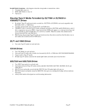
... read Type IV media only if media was formatted by a DLT7000 or DLT8000 is usable in what happens when the wrong media is inserted into a drive • Cleaning light comes on • Media light flashes or stays on • SDLT220 cannot read media created with original use and formatting information Dell DLT, VS and SDLT Media Handbook Page 9 drive gives no warning but backup software...
... read Type IV media only if media was formatted by a DLT7000 or DLT8000 is usable in what happens when the wrong media is inserted into a drive • Cleaning light comes on • Media light flashes or stays on • SDLT220 cannot read media created with original use and formatting information Dell DLT, VS and SDLT Media Handbook Page 9 drive gives no warning but backup software...


