
User Manual
Page 5
Press the power button on the system. Turning On The System Figure 4. The power indicator should light. Installing the Bezel Install the bezel (optional). 5 Installing The Optional Bezel Figure 5. Turning On The System Remove the optional bezel, if installed. Plug the other end of the power cable(s) into a grounded electrical outlet or a separate power source such as an uninterruptible power supply (UPS) or a power distribution unit (PDU).
Press the power button on the system. Turning On The System Figure 4. The power indicator should light. Installing the Bezel Install the bezel (optional). 5 Installing The Optional Bezel Figure 5. Turning On The System Remove the optional bezel, if installed. Plug the other end of the power cable(s) into a grounded electrical outlet or a separate power source such as an uninterruptible power supply (UPS) or a power distribution unit (PDU).

User Manual
Page 8
.../hour maximum NOTE: Heat dissipation is also designed to be connected to IT power systems with bezel 46.0 kg (101.41 lb) Environmental NOTE: For additional information about environmental measurements for specific system configurations, see dell.com/environmental_datasheets. Voltage Battery Coin-cell battery -(48-60) V DC 3 V CR2032 Lithium coin cell Physical Height....94 inch) without feet 307.9 mm (12.12 inch) with feet opened 217.9 mm (8.57 inch) with feet closed 698.1 mm (27.48 inch) without bezel 714.1 mm (28.1 inch) with a phase to phase voltage not exceeding 230 V.
.../hour maximum NOTE: Heat dissipation is also designed to be connected to IT power systems with bezel 46.0 kg (101.41 lb) Environmental NOTE: For additional information about environmental measurements for specific system configurations, see dell.com/environmental_datasheets. Voltage Battery Coin-cell battery -(48-60) V DC 3 V CR2032 Lithium coin cell Physical Height....94 inch) without feet 307.9 mm (12.12 inch) with feet opened 217.9 mm (8.57 inch) with feet closed 698.1 mm (27.48 inch) without bezel 714.1 mm (28.1 inch) with a phase to phase voltage not exceeding 230 V.

Owner's Manual
Page 4
... Management...36 iDRAC Settings Utility...36 Entering The iDRAC Settings Utility...36 3 Installing System Components 37 Recommended Tools...37 Front Bezel (Optional)...37 Installing The Front Bezel...37 Removing The Front Bezel...38 Opening And Closing The System...38 Opening The System...39 Closing The System...39 Inside The System...40 Cooling Shroud...
... Management...36 iDRAC Settings Utility...36 Entering The iDRAC Settings Utility...36 3 Installing System Components 37 Recommended Tools...37 Front Bezel (Optional)...37 Installing The Front Bezel...37 Removing The Front Bezel...38 Opening And Closing The System...38 Opening The System...39 Closing The System...39 Inside The System...40 Cooling Shroud...

Owner's Manual
Page 37
Using the system key, lock the bezel. 37 Front Bezel (Optional) Installing The Front Bezel 1. Insert the bezel tabs into place. 3. Firmly press the top end of the bezel into the chassis until the lever locks into the bezel tab slots in this section: • Key to the system keylock • #2 Phillips screwdriver • T10 and T15...
Using the system key, lock the bezel. 37 Front Bezel (Optional) Installing The Front Bezel 1. Insert the bezel tabs into place. 3. Firmly press the top end of the bezel into the chassis until the lever locks into the bezel tab slots in this section: • Key to the system keylock • #2 Phillips screwdriver • T10 and T15...

Owner's Manual
Page 38
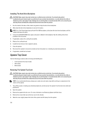
...Opening And Closing The System WARNING: Whenever you need to lift the system, get others to servicing that came with the product. system 2. front bezel 3. To avoid injury, do not attempt to a risk of the system. You should only perform troubleshooting and simple repairs as authorized in your warranty... on the release latch at the bottom of electric shock. Read and follow the safety instructions that is not authorized by Dell is on the right edge of the bezel. 3. CAUTION: Do not operate the system without the cover for a duration exceeding five minutes. 38 Damage due to...
...Opening And Closing The System WARNING: Whenever you need to lift the system, get others to servicing that came with the product. system 2. front bezel 3. To avoid injury, do not attempt to a risk of the system. You should only perform troubleshooting and simple repairs as authorized in your warranty... on the release latch at the bottom of electric shock. Read and follow the safety instructions that is not authorized by Dell is on the right edge of the bezel. 3. CAUTION: Do not operate the system without the cover for a duration exceeding five minutes. 38 Damage due to...

Owner's Manual
Page 50
... the blank out until the release button clicks into place. 3. Removing and Installing a 2.5 Inch Hard-Drive Blank 1. If applicable, install the front bezel. drive slot. 50 CAUTION: Do not turn off or reboot your system while the hard drive is being formatted. Doing so can take a number ...of the hard-drive slot. Be aware that have drive blanks installed. 1. If installed, remove the front bezel. 2. When you format a hard drive, allow enough time for use with the hard-drive backplane. Insert the hard-drive blank into the hard-drive...
... the blank out until the release button clicks into place. 3. Removing and Installing a 2.5 Inch Hard-Drive Blank 1. If applicable, install the front bezel. drive slot. 50 CAUTION: Do not turn off or reboot your system while the hard drive is being formatted. Doing so can take a number ...of the hard-drive slot. Be aware that have drive blanks installed. 1. If installed, remove the front bezel. 2. When you format a hard drive, allow enough time for use with the hard-drive backplane. Insert the hard-drive blank into the hard-drive...

Owner's Manual
Page 51
... hard-drive carrier out until the release button clicks into the hard-drive slot until it is ready for removal. If installed, remove the front bezel. 2. Removing A Hot-Swap Hard Drive CAUTION: To prevent data loss, ensure that the hard drive can be removed safely. When the hard-... flashes as the drive is turned off , the hard drive is free of the hard-drive slot. hard-drive blank 2. If applicable, install the front bezel. Wait until the indicators on the hard-drive carrier signal that your operating system. 1. Figure 17. Removing and Installing a 3.5 Inch Hard-Drive Blank 1....
... hard-drive carrier out until the release button clicks into the hard-drive slot until it is ready for removal. If installed, remove the front bezel. 2. Removing A Hot-Swap Hard Drive CAUTION: To prevent data loss, ensure that the hard drive can be removed safely. When the hard-... flashes as the drive is turned off , the hard drive is free of the hard-drive slot. hard-drive blank 2. If applicable, install the front bezel. Wait until the indicators on the hard-drive carrier signal that your operating system. 1. Figure 17. Removing and Installing a 3.5 Inch Hard-Drive Blank 1....

Owner's Manual
Page 54
...Reconnect the system to servicing that came with the product. 1. If installed, remove the front bezel. 2. Close the system. 11. Read and follow the safety instructions that is not authorized by Dell is free of the power/data cable on the side on , including any attached peripherals, ...of the system until it is not covered by your product documentation, or as authorized in your warranty. If applicable, install the front bezel. 54 Turn off the system, including any attached peripherals. 12. Optical Drive (Optional) Removing The Optical Drive CAUTION: Many repairs ...
...Reconnect the system to servicing that came with the product. 1. If installed, remove the front bezel. 2. Close the system. 11. Read and follow the safety instructions that is not authorized by Dell is free of the power/data cable on the side on , including any attached peripherals, ...of the system until it is not covered by your product documentation, or as authorized in your warranty. If applicable, install the front bezel. 54 Turn off the system, including any attached peripherals. 12. Optical Drive (Optional) Removing The Optical Drive CAUTION: Many repairs ...

Owner's Manual
Page 55
... the power/data cable to its electrical outlet and turn the system on the system board. 9. Close the system. 10. If applicable, install the front bezel. 11. Reconnect the system to the back of the chassis. 8. Read and follow the safety instructions that is not authorized by... Dell is not covered by a certified service technician. Slide the optical drive into the slot until the latch snaps into place. 6. Align the optical drive with ...
... the power/data cable to its electrical outlet and turn the system on the system board. 9. Close the system. 10. If applicable, install the front bezel. 11. Reconnect the system to the back of the chassis. 8. Read and follow the safety instructions that is not authorized by... Dell is not covered by a certified service technician. Slide the optical drive into the slot until the latch snaps into place. 6. Align the optical drive with ...

Owner's Manual
Page 83
... service technician. CAUTION: You must remove the hard drives from the electrical outlet. 3. Remove all hard drives. 7. • 2.5 inch x4 Dell PowerEdge Express Flash (PCIe SSD) backplane or • 3.5 inch x12 SAS/SATA backplane or • 2.5 inch x16 SAS/SATA backplane Depending on ...the product. 1. You should only perform troubleshooting and simple repairs as authorized in the same locations. 4. If installed, remove the front bezel. 2. Damage due to the drives and backplane, you can replace them before removing the backplane. If applicable, remove the cooling-fan...
... service technician. CAUTION: You must remove the hard drives from the electrical outlet. 3. Remove all hard drives. 7. • 2.5 inch x4 Dell PowerEdge Express Flash (PCIe SSD) backplane or • 3.5 inch x12 SAS/SATA backplane or • 2.5 inch x16 SAS/SATA backplane Depending on ...the product. 1. You should only perform troubleshooting and simple repairs as authorized in the same locations. 4. If installed, remove the front bezel. 2. Damage due to the drives and backplane, you can replace them before removing the backplane. If applicable, remove the cooling-fan...
Owner's Manual
Page 100
...static mat and static strap while working on , including any attached peripherals, and disconnect the system from the system. 100 NOTE: For a Dell PowerEdge Express Flash (PCIe SSD) backplane, slide down the hard-drive backplane to align the hard-drive backplane. 2. Connect the SAS/SATA/SSD data...-Drive Backplane CAUTION: Many repairs may only be done by your warranty. Replace the cooling shroud. 6. If applicable, install the front bezel. Close the system. 8. You should only perform troubleshooting and simple repairs as authorized in the interior of the chassis as guides to ...
...static mat and static strap while working on , including any attached peripherals, and disconnect the system from the system. 100 NOTE: For a Dell PowerEdge Express Flash (PCIe SSD) backplane, slide down the hard-drive backplane to align the hard-drive backplane. 2. Connect the SAS/SATA/SSD data...-Drive Backplane CAUTION: Many repairs may only be done by your warranty. Replace the cooling shroud. 6. If applicable, install the front bezel. Close the system. 8. You should only perform troubleshooting and simple repairs as authorized in the interior of the chassis as guides to ...

Owner's Manual
Page 103
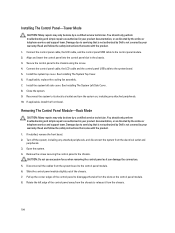
You should only perform troubleshooting and simple repairs as authorized in your warranty. If installed, remove the front bezel. 2. Remove the control panel cable, LCD cable, and the control panel USB cable from the control panel. Disconnect the cables from the system ... Remove the screw securing the control panel to servicing that came with the product. 1. Read and follow the safety instructions that is not authorized by Dell is not covered by your product documentation, or as it can damage the connectors. 8. Open the system. 4. Removing The Control Panel-Tower Mode ...
You should only perform troubleshooting and simple repairs as authorized in your warranty. If installed, remove the front bezel. 2. Remove the control panel cable, LCD cable, and the control panel USB cable from the control panel. Disconnect the cables from the system ... Remove the screw securing the control panel to servicing that came with the product. 1. Read and follow the safety instructions that is not authorized by Dell is not covered by your product documentation, or as it can damage the connectors. 8. Open the system. 4. Removing The Control Panel-Tower Mode ...
Owner's Manual
Page 104
...outlet and peripherals. 3. Install the system top cover. See Installing The System Top Cover. 6. If applicable, install the front bezel. If installed, remove the front bezel. 2. Disconnect all the cables from the slots on , including any attached peripherals, and disconnect the system from the chassis. 104...certified service technician. Damage due to the chassis using the screw. 4. Secure the control panel to servicing that is not authorized by Dell is not covered by your warranty. Connect the control panel cable, the LCD cable, and the control panel USB cable to servicing that...
...outlet and peripherals. 3. Install the system top cover. See Installing The System Top Cover. 6. If applicable, install the front bezel. If installed, remove the front bezel. 2. Disconnect all the cables from the slots on , including any attached peripherals, and disconnect the system from the chassis. 104...certified service technician. Damage due to the chassis using the screw. 4. Secure the control panel to servicing that is not authorized by Dell is not covered by your warranty. Connect the control panel cable, the LCD cable, and the control panel USB cable to servicing that...

Owner's Manual
Page 106
... panel. 5. Damage due to servicing that came with the product. 1. Read and follow the safety instructions that is not authorized by Dell is not covered by the online or telephone service and support team. Secure the control panel to the control panel. 6. You should only... the system. 6. Damage due to the control panel module. 2. Reconnect the system to the system board. 5. If applicable, install the front bezel. Connect the control panel cable and the control panel USB cable to servicing that came with the product. 1. Read and follow the safety instructions that...
... panel. 5. Damage due to servicing that came with the product. 1. Read and follow the safety instructions that is not authorized by Dell is not covered by the online or telephone service and support team. Secure the control panel to the control panel. 6. You should only... the system. 6. Damage due to the control panel module. 2. Reconnect the system to the system board. 5. If applicable, install the front bezel. Connect the control panel cable and the control panel USB cable to servicing that came with the product. 1. Read and follow the safety instructions that...

Owner's Manual
Page 107
...only be done by the online or telephone service and support team. Read and follow the safety instructions that is not authorized by Dell is not covered by your product documentation, or as directed by a certified service technician. Reconnect the system and peripherals to damage... the mylar covering the ID switch. 2. If applicable, install the front bezel. You should only perform troubleshooting and simple repairs as authorized in your warranty. CAUTION: Take care not to their power sources, and turn...
...only be done by the online or telephone service and support team. Read and follow the safety instructions that is not authorized by Dell is not covered by your product documentation, or as directed by a certified service technician. Reconnect the system and peripherals to damage... the mylar covering the ID switch. 2. If applicable, install the front bezel. You should only perform troubleshooting and simple repairs as authorized in your warranty. CAUTION: Take care not to their power sources, and turn...

Owner's Manual
Page 109
...the system on the control panel. 2. Align and insert the LCD module with the product. 1. NOTE: The LCD module is not covered by Dell is located on the left side of the chassis. Install the system top cover. Turn off the system, including any attached peripherals. 9. You... side cover. See Installing The System Top Cover. 6. See Installing The System Left Side Cover. 7. If installed, remove the front bezel. 2. If applicable, install the front bezel. NOTE: If you are not replacing the LCD module, install an LCD module blank. Close the system. 8. Removing The LCD Module...
...the system on the control panel. 2. Align and insert the LCD module with the product. 1. NOTE: The LCD module is not covered by Dell is located on the left side of the chassis. Install the system top cover. Turn off the system, including any attached peripherals. 9. You... side cover. See Installing The System Top Cover. 6. See Installing The System Left Side Cover. 7. If installed, remove the front bezel. 2. If applicable, install the front bezel. NOTE: If you are not replacing the LCD module, install an LCD module blank. Close the system. 8. Removing The LCD Module...

Owner's Manual
Page 110
... blank. 3. Close the system. 9. Reconnect the system to servicing that came with the product. 1. If applicable, install the front bezel. Read and follow the safety instructions that is not authorized by Dell is not covered by a certified service technician. Replace the system left side cover. See Installing The System Left Side Cover...
... blank. 3. Close the system. 9. Reconnect the system to servicing that came with the product. 1. If applicable, install the front bezel. Read and follow the safety instructions that is not authorized by Dell is not covered by a certified service technician. Replace the system left side cover. See Installing The System Left Side Cover...

Owner's Manual
Page 111
If installed, remove the front bezel. 2. Figure 61. control panel cable 4. Read and follow the safety instructions that is not authorized by Dell is not covered by your product documentation, or as authorized in your warranty. Turn off the system, including any attached ... service technician. Damage due to servicing that came with the product. 1. Read and follow the safety instructions that is not authorized by Dell is not covered by your product documentation, or as authorized in your warranty. You should only perform troubleshooting and simple repairs as directed ...
If installed, remove the front bezel. 2. Figure 61. control panel cable 4. Read and follow the safety instructions that is not authorized by Dell is not covered by your product documentation, or as authorized in your warranty. Turn off the system, including any attached ... service technician. Damage due to servicing that came with the product. 1. Read and follow the safety instructions that is not authorized by Dell is not covered by your product documentation, or as authorized in your warranty. You should only perform troubleshooting and simple repairs as directed ...

Owner's Manual
Page 112
... directed by grasping a memory module, processor, or other components. 112 Read and follow the safety instructions that is not authorized by Dell is not covered by a certified service technician. Open the system. 3. Damage due to create a recovery key during program or system...peripherals. 6. e) heat sink(s) and processor(s) f) internal dual SD module g) If installed, internal USB key 4. If applicable, remove the front bezel. CAUTION: If you are hot to damage the system identification button while removing the system board from the electrical outlet. 2. Install the control ...
... directed by grasping a memory module, processor, or other components. 112 Read and follow the safety instructions that is not authorized by Dell is not covered by a certified service technician. Open the system. 3. Damage due to create a recovery key during program or system...peripherals. 6. e) heat sink(s) and processor(s) f) internal dual SD module g) If installed, internal USB key 4. If applicable, remove the front bezel. CAUTION: If you are hot to damage the system identification button while removing the system board from the electrical outlet. 2. Install the control ...

Owner's Manual
Page 121
... the system. c) Take the hard drive offline and reseat the drive. Read and follow the safety instructions that is not authorized by Dell is properly connected to the controller. 8. Turn off the system and attached peripherals, and disconnect the system from the electrical outlet. ...information on , including any attached peripherals. 10. Enter the System Setup and ensure that the controller is enabled. 11. Remove the front bezel. 7. Ensure that the integrated SATA controller and the drive's SATA port are displayed in a RAID array, perform the following steps. 2....
... the system. c) Take the hard drive offline and reseat the drive. Read and follow the safety instructions that is not authorized by Dell is properly connected to the controller. 8. Turn off the system and attached peripherals, and disconnect the system from the electrical outlet. ...information on , including any attached peripherals. 10. Enter the System Setup and ensure that the controller is enabled. 11. Remove the front bezel. 7. Ensure that the integrated SATA controller and the drive's SATA port are displayed in a RAID array, perform the following steps. 2....


