
User Manual
Page 6
... comprehensive hardware training and 6 To install an operating system for the first time, see your system's hard drive. You must consider any media of the software installed on support.dell.com/manuals and read the Dell Software License Agreement that shipped with your country or region from the top of the agreement, call 800...
... comprehensive hardware training and 6 To install an operating system for the first time, see your system's hard drive. You must consider any media of the software installed on support.dell.com/manuals and read the Dell Software License Agreement that shipped with your country or region from the top of the agreement, call 800...
Owner's Manual
Page 3
...-Panel Features And Indicators...9 Front-Panel Features And Indicators-Rack Mode 12 LCD Panel Features...14 Home Screen...14 Setup Menu...15 View Menu...15 Hard-Drive Indicator Patterns...16 Back-Panel Features And Indicators...17 NIC Indicator Codes...19 Power Indicator Codes...19 Other Information You May Need...20 2 Using The...
...-Panel Features And Indicators...9 Front-Panel Features And Indicators-Rack Mode 12 LCD Panel Features...14 Home Screen...14 Setup Menu...15 View Menu...15 Hard-Drive Indicator Patterns...16 Back-Panel Features And Indicators...17 NIC Indicator Codes...19 Power Indicator Codes...19 Other Information You May Need...20 2 Using The...

Owner's Manual
Page 4
... Installing Memory Modules...49 Hard Drives...49 Removing A 2.5 Inch Hard-Drive Blank...50 Installing A 2.5 Inch Hard-Drive Blank...50 Removing A 3.5 Inch Hard-Drive Blank...50 Installing A 3.5 Inch Hard-Drive Blank...51 Removing A Hot-Swap Hard Drive...51 Installing A Hot-Swap Hard Drive...52 Removing A Hard Drive From A Hard-Drive Carrier 53 Installing A Hard Drive Into A Hard-Drive Carrier 53 Optical Drive (Optional)...54 Removing The Optical Drive...54 Installing The Optical Drive...55 Cooling Fans...
... Installing Memory Modules...49 Hard Drives...49 Removing A 2.5 Inch Hard-Drive Blank...50 Installing A 2.5 Inch Hard-Drive Blank...50 Removing A 3.5 Inch Hard-Drive Blank...50 Installing A 3.5 Inch Hard-Drive Blank...51 Removing A Hot-Swap Hard Drive...51 Installing A Hot-Swap Hard Drive...52 Removing A Hard Drive From A Hard-Drive Carrier 53 Installing A Hard Drive Into A Hard-Drive Carrier 53 Optical Drive (Optional)...54 Removing The Optical Drive...54 Installing The Optical Drive...55 Cooling Fans...

Owner's Manual
Page 5
... A DC Power Supply...80 Removing The Power Supply Blank...81 Installing The Power Supply Blank...81 System Battery...81 Replacing The System Battery...81 Hard-Drive Backplane...82 Removing The Hard-Drive Backplane...83 Installing The Hard-Drive Backplane...100 System Top Cover...100 Removing The System Top Cover...100 Installing The System Top Cover...101
... A DC Power Supply...80 Removing The Power Supply Blank...81 Installing The Power Supply Blank...81 System Battery...81 Replacing The System Battery...81 Hard-Drive Backplane...82 Removing The Hard-Drive Backplane...83 Installing The Hard-Drive Backplane...100 System Top Cover...100 Removing The System Top Cover...100 Installing The System Top Cover...101

Owner's Manual
Page 6
... Cooling Problems...118 Troubleshooting Cooling Fans...119 Troubleshooting System Memory...119 Troubleshooting An Internal USB Key...120 Troubleshooting An SD Card...120 Troubleshooting An Optical Drive...121 Troubleshooting A Hard Drive...121 Troubleshooting Expansion Cards...122
... Cooling Problems...118 Troubleshooting Cooling Fans...119 Troubleshooting System Memory...119 Troubleshooting An Internal USB Key...120 Troubleshooting An SD Card...120 Troubleshooting An Optical Drive...121 Troubleshooting A Hard Drive...121 Troubleshooting Expansion Cards...122

Owner's Manual
Page 9
Front-Panel Features and Indicators-2.5 Inch Hard-Drive Chassis 9 1 About Your System Front-Panel Features And Indicators Figure 1.
Front-Panel Features and Indicators-2.5 Inch Hard-Drive Chassis 9 1 About Your System Front-Panel Features And Indicators Figure 1.

Owner's Manual
Page 10
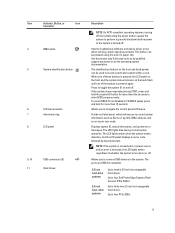
The power button controls the power supply output to insert a vFlash media card. 3 Power-on indicator, power button The power-on indicator lights when the system power is on. Front-Panel Features and Indicators-3.5 Inch Hard-Drive Chassis Item Indicator, Button, or Icon Description Connector 1 Optical drive (optional) One optional SATA DVD-ROM drive or DVD+/-RW drive. 2 vFlash media card slot Allows you to the system. 10 Figure 2.
The power button controls the power supply output to insert a vFlash media card. 3 Power-on indicator, power button The power-on indicator lights when the system power is on. Front-Panel Features and Indicators-3.5 Inch Hard-Drive Chassis Item Indicator, Button, or Icon Description Connector 1 Optical drive (optional) One optional SATA DVD-ROM drive or DVD+/-RW drive. 2 vFlash media card slot Allows you to the system. 10 Figure 2.
Owner's Manual
Page 11
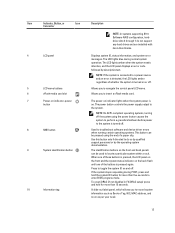
... using the end of the buttons is pressed again. When one of these buttons is turned on and off . 9, 10 USB connectors (2) 11 Hard drives Allows you to do so by qualified support personnel or by descriptive text. The LCD lights amber when the system needs attention, and the LCD...off . The LCD lights blue during POST, press and hold for more than five seconds to locate a particular system within a rack. Press to four Dell PowerEdge Express Flash devices (PCIe SSDs). To reset iDRAC (if not disabled in F2 iDRAC setup) press and hold the system ID button for more than...
... using the end of the buttons is pressed again. When one of these buttons is turned on and off . 9, 10 USB connectors (2) 11 Hard drives Allows you to do so by qualified support personnel or by descriptive text. The LCD lights amber when the system needs attention, and the LCD...off . The LCD lights blue during POST, press and hold for more than five seconds to locate a particular system within a rack. Press to four Dell PowerEdge Express Flash devices (PCIe SSDs). To reset iDRAC (if not disabled in F2 iDRAC setup) press and hold the system ID button for more than...

Owner's Manual
Page 12
... RAID configuration, harddrive slots 4 through 7 do not support any hard drives and are USB 2.0-compliant. 2 Optical drive (optional) One optional SATA DVD-ROM drive or DVD+/-RW drive. 3 Hard-drive bay 3.5 inch hard-drive systems Up to four Dell PowerEdge Express Flash devices (PCIe SSDs). 2.5 inch hard- Up to twelve 3.5 inch hot-swappable hard drives. drive systems Up to four PCIe SSDs. 12 Up to...
... RAID configuration, harddrive slots 4 through 7 do not support any hard drives and are USB 2.0-compliant. 2 Optical drive (optional) One optional SATA DVD-ROM drive or DVD+/-RW drive. 3 Hard-drive bay 3.5 inch hard-drive systems Up to four Dell PowerEdge Express Flash devices (PCIe SSDs). 2.5 inch hard- Up to twelve 3.5 inch hot-swappable hard drives. drive systems Up to four PCIe SSDs. 12 Up to...
Owner's Manual
Page 13
... hold the system ID button for more than 15 seconds. The power button controls the power supply output to do not support any hard drives and are installed with hard-drive blanks. 4 LCD panel 5 LCD menu buttons 6 vFlash media card slot 7 Power-on indicator lights when the system power is turned off . The identification...
... hold the system ID button for more than 15 seconds. The power button controls the power supply output to do not support any hard drives and are installed with hard-drive blanks. 4 LCD panel 5 LCD menu buttons 6 vFlash media card slot 7 Power-on indicator lights when the system power is turned off . The identification...

Owner's Manual
Page 16
...three seconds, amber three seconds, and off until all hard drives are not ready for insertion or removal NOTE: The drive status indicator remains off six seconds Predicted drive failure Drive failed Drive rebuilding Drive online Rebuild aborted 16 Blinks green, amber, and off... drive or preparing for removal Drive ready for insertion or removal during this time. hard-drive status indicator (green and amber) NOTE: If the hard drive is turned on the right side) does not function and remains off. Hard-Drive Indicators 1. hard-drive activity indicator (green) 2. Drives ...
...three seconds, amber three seconds, and off until all hard drives are not ready for insertion or removal NOTE: The drive status indicator remains off six seconds Predicted drive failure Drive failed Drive rebuilding Drive online Rebuild aborted 16 Blinks green, amber, and off... drive or preparing for removal Drive ready for insertion or removal during this time. hard-drive status indicator (green and amber) NOTE: If the hard drive is turned on the right side) does not function and remains off. Hard-Drive Indicators 1. hard-drive activity indicator (green) 2. Drives ...

Owner's Manual
Page 40
... on the components are marked orange and touch-points on , including any attached peripherals. Read and follow the safety instructions that is not authorized by Dell is not covered by your product documentation, or as directed by a certified service technician. Inside the System 1. cooling fan assembly (optional) 2. heat sinks (2) Cooling Shroud... holder 3. Figure 12. 4. Turn the cover latch release lock clockwise to servicing that came with the product. Damage due to the locked position. 5. cooling shroud 4. hard-drive backplane 40
... on the components are marked orange and touch-points on , including any attached peripherals. Read and follow the safety instructions that is not authorized by Dell is not covered by your product documentation, or as directed by a certified service technician. Inside the System 1. cooling fan assembly (optional) 2. heat sinks (2) Cooling Shroud... holder 3. Figure 12. 4. Turn the cover latch release lock clockwise to servicing that came with the product. Damage due to the locked position. 5. cooling shroud 4. hard-drive backplane 40

Owner's Manual
Page 49
... levers latch into a locked position. Press down on the main System Setup screen. CAUTION: Before attempting to remove or install a hard drive while the system is properly seated in the socket, the levers on the memory module socket align with your thumbs until the memory.... 12. Press to install the remaining memory modules. 10. Run the system memory test in hotswappable hard-drive carriers that is not authorized by Dell is incorrect, one way. 8. Hard Drives All hard drives connect to the system board through step 9 of this procedure to enter the System Setup, and check...
... levers latch into a locked position. Press down on the main System Setup screen. CAUTION: Before attempting to remove or install a hard drive while the system is properly seated in the socket, the levers on the memory module socket align with your thumbs until the memory.... 12. Press to install the remaining memory modules. 10. Run the system memory test in hotswappable hard-drive carriers that is not authorized by Dell is incorrect, one way. 8. Hard Drives All hard drives connect to the system board through step 9 of this procedure to enter the System Setup, and check...

Owner's Manual
Page 50
... bezel. 2. Removing A 3.5 Inch Hard-Drive Blank CAUTION: To maintain proper system cooling, all empty hard-drive slots must have hard-drive blanks installed. 1. Grasp the front of the hard-drive blank, press the release button and slide the blank out until it is being formatted. NOTE: Use only hard drives that high-capacity hard drives can cause a hard drive failure. hard-drive blank 2. If installed, remove...
... bezel. 2. Removing A 3.5 Inch Hard-Drive Blank CAUTION: To maintain proper system cooling, all empty hard-drive slots must have hard-drive blanks installed. 1. Grasp the front of the hard-drive blank, press the release button and slide the blank out until it is being formatted. NOTE: Use only hard drives that high-capacity hard drives can cause a hard drive failure. hard-drive blank 2. If installed, remove...

Owner's Manual
Page 51
... hard-drive blanks installed. 4. Slide the hard-drive carrier out until the release button clicks into the hard-drive slot until it is ready for removal. 2. Insert the hard-drive blank into place. 3. When the hard-drive indicators are off . Insert a hard-drive blank in the empty hard-drive slot. 51 Removing and Installing a 3.5 Inch Hard-Drive Blank 1. release button Installing A 3.5 Inch Hard-Drive Blank 1. Removing A Hot-Swap Hard Drive...
... hard-drive blanks installed. 4. Slide the hard-drive carrier out until the release button clicks into the hard-drive slot until it is ready for removal. 2. Insert the hard-drive blank into place. 3. When the hard-drive indicators are off . Insert a hard-drive blank in the empty hard-drive slot. 51 Removing and Installing a 3.5 Inch Hard-Drive Blank 1. release button Installing A 3.5 Inch Hard-Drive Blank 1. Removing A Hot-Swap Hard Drive...

Owner's Manual
Page 52
... sure that you wish to lock the hard drive in the hard-drive carrier. 3. CAUTION: When installing a hard drive, ensure that your warranty. Press the release button on , the hard drive automatically begins to rebuild. Inserting a hard-drive carrier and attempting to lock its handle next to servicing that is not authorized by Dell is blank or contains data that the...
... sure that you wish to lock the hard drive in the hard-drive carrier. 3. CAUTION: When installing a hard drive, ensure that your warranty. Press the release button on , the hard drive automatically begins to rebuild. Inserting a hard-drive carrier and attempting to lock its handle next to servicing that is not authorized by Dell is blank or contains data that the...

Owner's Manual
Page 53
Figure 19. hard-drive carrier 2. screws (4) Installing A Hard Drive Into A Hard-Drive Carrier CAUTION: Many repairs may only be flush with the connector end of the hard drive toward the back. 2. Removing and Installing a Hard Drive Into a Hard-Drive Carrier 1. Read and follow the safety instructions that is not authorized by Dell is not covered by your product documentation, or as directed by a certified...
Figure 19. hard-drive carrier 2. screws (4) Installing A Hard Drive Into A Hard-Drive Carrier CAUTION: Many repairs may only be flush with the connector end of the hard drive toward the back. 2. Removing and Installing a Hard Drive Into a Hard-Drive Carrier 1. Read and follow the safety instructions that is not authorized by Dell is not covered by your product documentation, or as directed by a certified...

Owner's Manual
Page 63
... the card by the online or telephone service and support team. Place the system upright. 12. On systems that is not authorized by Dell is not covered by a certified service technician. Turn off the system, including any attached peripherals, and disconnect the system from the GPU ... or/and the power cables from the electrical outlet and peripherals. 2. On systems that came with four double-width GPU cards, the hard-drive setting must be installed: - On systems with Express Flash configuration supports a maximum of the card guides. 8. Removing An Expansion Card CAUTION...
... the card by the online or telephone service and support team. Place the system upright. 12. On systems that is not authorized by Dell is not covered by a certified service technician. Turn off the system, including any attached peripherals, and disconnect the system from the GPU ... or/and the power cables from the electrical outlet and peripherals. 2. On systems that came with four double-width GPU cards, the hard-drive setting must be installed: - On systems with Express Flash configuration supports a maximum of the card guides. 8. Removing An Expansion Card CAUTION...

Owner's Manual
Page 82
... x8 SAS/SATA backplane or 82 Enter the System Setup to the battery connector, you must firmly support the connector while installing or removing a battery. 6. Hard-Drive Backplane Depending on , including any attached peripherals, and disconnect the system from the electrical outlet and peripherals. 2.
... x8 SAS/SATA backplane or 82 Enter the System Setup to the battery connector, you must firmly support the connector while installing or removing a battery. 6. Hard-Drive Backplane Depending on , including any attached peripherals, and disconnect the system from the electrical outlet and peripherals. 2.

Owner's Manual
Page 83
...8226; 2.5 inch x4 Dell PowerEdge Express Flash (PCIe SSD) backplane or • 3.5 inch x12 SAS/SATA backplane or • 2.5 inch x16 SAS/SATA backplane Depending on the release pin and pull the backplane upward and out from the backplane. 8. Damage due to the drives and backplane, you can...SATA backplane and 2.5 inch x4 PCIe SSD backplane • 2.5 inch x16 SAS/SATA backplane and 2.5 inch x4 PCIe SSD backplane Removing The Hard-Drive Backplane CAUTION: Many repairs may only be done by a certified service technician. CAUTION: To prevent damage to servicing that came with the product. ...
...8226; 2.5 inch x4 Dell PowerEdge Express Flash (PCIe SSD) backplane or • 3.5 inch x12 SAS/SATA backplane or • 2.5 inch x16 SAS/SATA backplane Depending on the release pin and pull the backplane upward and out from the backplane. 8. Damage due to the drives and backplane, you can...SATA backplane and 2.5 inch x4 PCIe SSD backplane • 2.5 inch x16 SAS/SATA backplane and 2.5 inch x4 PCIe SSD backplane Removing The Hard-Drive Backplane CAUTION: Many repairs may only be done by a certified service technician. CAUTION: To prevent damage to servicing that came with the product. ...


