
User Manual
Page 6
... If you purchased with your Owner's Manual. For customers in other documents. NOTE: Always check for the latest information on supported operating systems. Dell Software License Agreement Before using your system, read the updates first because they often supersede information in the United States, call the customer assistance telephone...information about system features and describes how to the operating system, system management software, system updates, and system components that came with your system's hard drive. NOTE: See dell.com/ossupport for updates on your system...
... If you purchased with your Owner's Manual. For customers in other documents. NOTE: Always check for the latest information on supported operating systems. Dell Software License Agreement Before using your system, read the updates first because they often supersede information in the United States, call the customer assistance telephone...information about system features and describes how to the operating system, system management software, system updates, and system components that came with your system's hard drive. NOTE: See dell.com/ossupport for updates on your system...
Owner's Manual
Page 3
...-Panel Features And Indicators...9 Front-Panel Features And Indicators-Rack Mode 12 LCD Panel Features...14 Home Screen...14 Setup Menu...15 View Menu...15 Hard-Drive Indicator Patterns...16 Back-Panel Features And Indicators...17 NIC Indicator Codes...19 Power Indicator Codes...19 Other Information You May Need...20 2 Using The...
...-Panel Features And Indicators...9 Front-Panel Features And Indicators-Rack Mode 12 LCD Panel Features...14 Home Screen...14 Setup Menu...15 View Menu...15 Hard-Drive Indicator Patterns...16 Back-Panel Features And Indicators...17 NIC Indicator Codes...19 Power Indicator Codes...19 Other Information You May Need...20 2 Using The...

Owner's Manual
Page 4
... Installing Memory Modules...49 Hard Drives...49 Removing A 2.5 Inch Hard-Drive Blank...50 Installing A 2.5 Inch Hard-Drive Blank...50 Removing A 3.5 Inch Hard-Drive Blank...50 Installing A 3.5 Inch Hard-Drive Blank...51 Removing A Hot-Swap Hard Drive...51 Installing A Hot-Swap Hard Drive...52 Removing A Hard Drive From A Hard-Drive Carrier 53 Installing A Hard Drive Into A Hard-Drive Carrier 53 Optical Drive (Optional)...54 Removing The Optical Drive...54 Installing The Optical Drive...55 Cooling Fans...
... Installing Memory Modules...49 Hard Drives...49 Removing A 2.5 Inch Hard-Drive Blank...50 Installing A 2.5 Inch Hard-Drive Blank...50 Removing A 3.5 Inch Hard-Drive Blank...50 Installing A 3.5 Inch Hard-Drive Blank...51 Removing A Hot-Swap Hard Drive...51 Installing A Hot-Swap Hard Drive...52 Removing A Hard Drive From A Hard-Drive Carrier 53 Installing A Hard Drive Into A Hard-Drive Carrier 53 Optical Drive (Optional)...54 Removing The Optical Drive...54 Installing The Optical Drive...55 Cooling Fans...

Owner's Manual
Page 5
... A DC Power Supply...80 Removing The Power Supply Blank...81 Installing The Power Supply Blank...81 System Battery...81 Replacing The System Battery...81 Hard-Drive Backplane...82 Removing The Hard-Drive Backplane...83 Installing The Hard-Drive Backplane...100 System Top Cover...100 Removing The System Top Cover...100 Installing The System Top Cover...101
... A DC Power Supply...80 Removing The Power Supply Blank...81 Installing The Power Supply Blank...81 System Battery...81 Replacing The System Battery...81 Hard-Drive Backplane...82 Removing The Hard-Drive Backplane...83 Installing The Hard-Drive Backplane...100 System Top Cover...100 Removing The System Top Cover...100 Installing The System Top Cover...101

Owner's Manual
Page 6
... Cooling Problems...118 Troubleshooting Cooling Fans...119 Troubleshooting System Memory...119 Troubleshooting An Internal USB Key...120 Troubleshooting An SD Card...120 Troubleshooting An Optical Drive...121 Troubleshooting A Hard Drive...121 Troubleshooting Expansion Cards...122
... Cooling Problems...118 Troubleshooting Cooling Fans...119 Troubleshooting System Memory...119 Troubleshooting An Internal USB Key...120 Troubleshooting An SD Card...120 Troubleshooting An Optical Drive...121 Troubleshooting A Hard Drive...121 Troubleshooting Expansion Cards...122

Owner's Manual
Page 9
1 About Your System Front-Panel Features And Indicators Figure 1. Front-Panel Features and Indicators-2.5 Inch Hard-Drive Chassis 9
1 About Your System Front-Panel Features And Indicators Figure 1. Front-Panel Features and Indicators-2.5 Inch Hard-Drive Chassis 9

Owner's Manual
Page 10
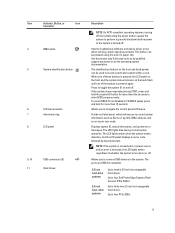
Front-Panel Features and Indicators-3.5 Inch Hard-Drive Chassis Item Indicator, Button, or Icon Description Connector 1 Optical drive (optional) One optional SATA DVD-ROM drive or DVD+/-RW drive. 2 vFlash media card slot Allows you to the system. 10 The power button controls the power supply output to insert a vFlash media card. 3 Power-on indicator, power button The power-on indicator lights when the system power is on. Figure 2.
Front-Panel Features and Indicators-3.5 Inch Hard-Drive Chassis Item Indicator, Button, or Icon Description Connector 1 Optical drive (optional) One optional SATA DVD-ROM drive or DVD+/-RW drive. 2 vFlash media card slot Allows you to the system. 10 The power button controls the power supply output to insert a vFlash media card. 3 Power-on indicator, power button The power-on indicator lights when the system power is on. Figure 2.
Owner's Manual
Page 11
.... A slide-out label panel, which allows you to navigate the control panel LCD menu. The ports are USB 2.0-compliant. 3.5 inch hard-drive systems 2.5 inch hard- Use this button only if directed to do so by qualified support personnel or by descriptive text. NOTE: If the system is connected ..., the LCD panel on the front and the system status indicator on the back flash until one of a paper clip. Up to four Dell PowerEdge Express Flash devices (PCIe SSDs). Item Indicator, Button, or Icon Description Connector NOTE: On ACPI-compliant operating systems, turning off the system ...
.... A slide-out label panel, which allows you to navigate the control panel LCD menu. The ports are USB 2.0-compliant. 3.5 inch hard-drive systems 2.5 inch hard- Use this button only if directed to do so by qualified support personnel or by descriptive text. NOTE: If the system is connected ..., the LCD panel on the front and the system status indicator on the back flash until one of a paper clip. Up to four Dell PowerEdge Express Flash devices (PCIe SSDs). Item Indicator, Button, or Icon Description Connector NOTE: On ACPI-compliant operating systems, turning off the system ...

Owner's Manual
Page 12
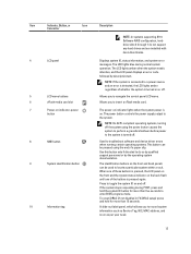
... Connector 1, 11 USB connectors (2) Allows you to connect USB devices to thirty two 2.5 inch hot-swappable hard drives. drive systems Up to the system. The ports are installed with the rack ears and does not have the stabilizer... hard drives and are USB 2.0-compliant. 2 Optical drive (optional) One optional SATA DVD-ROM drive or DVD+/-RW drive. 3 Hard-drive bay 3.5 inch hard-drive systems Up to twelve 3.5 inch hot-swappable hard drives. Up to four Dell PowerEdge Express Flash devices (PCIe SSDs). 2.5 inch hard- Front-Panel Features and Indicators-2.5 Inch Hard-Drive ...
... Connector 1, 11 USB connectors (2) Allows you to connect USB devices to thirty two 2.5 inch hot-swappable hard drives. drive systems Up to the system. The ports are installed with the rack ears and does not have the stabilizer... hard drives and are USB 2.0-compliant. 2 Optical drive (optional) One optional SATA DVD-ROM drive or DVD+/-RW drive. 3 Hard-drive bay 3.5 inch hard-drive systems Up to twelve 3.5 inch hot-swappable hard drives. Up to four Dell PowerEdge Express Flash devices (PCIe SSDs). 2.5 inch hard- Front-Panel Features and Indicators-2.5 Inch Hard-Drive ...
Owner's Manual
Page 13
Allows you to troubleshoot software and device driver errors when running certain operating systems. This button can be used to do not support any hard drives and are installed with hard-drive blanks. 4 LCD panel 5 LCD menu buttons 6 vFlash media card slot 7 Power-on the front and back panels can be pressed using the power...
Allows you to troubleshoot software and device driver errors when running certain operating systems. This button can be used to do not support any hard drives and are installed with hard-drive blanks. 4 LCD panel 5 LCD menu buttons 6 vFlash media card slot 7 Power-on the front and back panels can be pressed using the power...

Owner's Manual
Page 16
... Blinks green slowly Steady green Blinks green three seconds, amber three seconds, and off . hard-drive activity indicator (green) 2. Hard-Drive Indicator Patterns Figure 5. Hard-Drive Indicators 1. Drives are not ready for insertion or removal NOTE: The drive status indicator remains off until all hard drives are initialized after the system is in Advanced Host Controller Interface (AHCI) mode, the...
... Blinks green slowly Steady green Blinks green three seconds, amber three seconds, and off . hard-drive activity indicator (green) 2. Hard-Drive Indicator Patterns Figure 5. Hard-Drive Indicators 1. Drives are not ready for insertion or removal NOTE: The drive status indicator remains off until all hard drives are initialized after the system is in Advanced Host Controller Interface (AHCI) mode, the...

Owner's Manual
Page 40
... , including any attached peripherals. Reconnect the system to the locked position. 5. Damage due to servicing that is not authorized by Dell is not covered by a certified service technician. PCIe card holder 7. hard-drive backplane 40 4. Turn the cover latch release lock clockwise to its electrical outlet and turn the system on the components...
... , including any attached peripherals. Reconnect the system to the locked position. 5. Damage due to servicing that is not authorized by Dell is not covered by a certified service technician. PCIe card holder 7. hard-drive backplane 40 4. Turn the cover latch release lock clockwise to its electrical outlet and turn the system on the components...

Owner's Manual
Page 49
... to ensure that the memory modules are hot to the touch for the memory modules to install the remaining memory modules. 10. Hard Drives All hard drives connect to the system board through step 9 of this procedure to cool before handling them. Press down . Lay the system on...You should have memory modules installed. 9. Damage due to support hot-swap hard drive removal and insertion. 49 Replace the cooling shroud. 11. Read and follow the safety instructions that is not authorized by Dell is configured correctly to servicing that came with the levers on , including any...
... to ensure that the memory modules are hot to the touch for the memory modules to install the remaining memory modules. 10. Hard Drives All hard drives connect to the system board through step 9 of this procedure to cool before handling them. Press down . Lay the system on...You should have memory modules installed. 9. Damage due to support hot-swap hard drive removal and insertion. 49 Replace the cooling shroud. 11. Read and follow the safety instructions that is not authorized by Dell is configured correctly to servicing that came with the levers on , including any...

Owner's Manual
Page 50
...hard drives that high-capacity hard drives can cause a hard drive failure. Removing A 2.5 Inch Hard-Drive Blank CAUTION: To maintain proper system cooling, all empty hard-drive slots must have been tested and approved for the formatting to format. Press the release button and slide the hard-drive blank out until it is free of the hard- Insert the hard-drive...off or reboot your system while the hard drive is free of the hard-drive slot. Be aware that have hard-drive blanks installed. 1. Figure 16. release button Installing A 2.5 Inch Hard-Drive Blank 1. If installed, remove the ...
...hard drives that high-capacity hard drives can cause a hard drive failure. Removing A 2.5 Inch Hard-Drive Blank CAUTION: To maintain proper system cooling, all empty hard-drive slots must have been tested and approved for the formatting to format. Press the release button and slide the hard-drive blank out until it is free of the hard- Insert the hard-drive...off or reboot your system while the hard drive is free of the hard-drive slot. Be aware that have hard-drive blanks installed. 1. Figure 16. release button Installing A 2.5 Inch Hard-Drive Blank 1. If installed, remove the ...

Owner's Manual
Page 51
... ready for removal. 2. Press the release button to open the hard-drive carrier release handle. 3. Insert a hard-drive blank in the empty hard-drive slot. 51 If the hard drive is online, the green activity/fault indicator flashes as the drive is turned off , the hard drive is free of the hard-drive slot. See the documentation supplied with your operating system supports...
... ready for removal. 2. Press the release button to open the hard-drive carrier release handle. 3. Insert a hard-drive blank in the empty hard-drive slot. 51 If the hard drive is online, the green activity/fault indicator flashes as the drive is turned off , the hard drive is free of the hard-drive slot. See the documentation supplied with your operating system supports...

Owner's Manual
Page 52
... Dell is not covered by your operating system supports hot-swap drive installation. CAUTION: Combining SAS and SATA hard drives in place. 52 CAUTION: When a replacement hot-swappable hard drive is installed and the system is not supported. hard drive 3. Inserting a hard-drive carrier and attempting to lock its handle next to rebuild. Close the hard-drive carrier handle to lock the hard drive...
... Dell is not covered by your operating system supports hot-swap drive installation. CAUTION: Combining SAS and SATA hard drives in place. 52 CAUTION: When a replacement hot-swappable hard drive is installed and the system is not supported. hard drive 3. Inserting a hard-drive carrier and attempting to lock its handle next to rebuild. Close the hard-drive carrier handle to lock the hard drive...

Owner's Manual
Page 53
... servicing that came with the connector end of holes on the hard-drive carrier. Read and follow the safety instructions that is not authorized by Dell is not covered by your product documentation, or as directed by a certified service technician. screws (4) Installing A Hard Drive Into A Hard-Drive Carrier CAUTION: Many repairs may only be flush with the...
... servicing that came with the connector end of holes on the hard-drive carrier. Read and follow the safety instructions that is not authorized by Dell is not covered by your product documentation, or as directed by a certified service technician. screws (4) Installing A Hard Drive Into A Hard-Drive Carrier CAUTION: Many repairs may only be flush with the...

Owner's Manual
Page 63
...its electrical outlet and turn the system on, including any other add-on cards. • On a system with four double-width GPU cards, the hard-drive setting must be installed: - NOTE: When you have the 1100 W power supply. If applicable, disconnect the data cables for the PERC card or/and... should only perform troubleshooting and simple repairs as directed by a certified service technician. Read and follow the safety instructions that is not authorized by Dell is not covered by its edge, pull the card up to remove it from the card connector, and continue to pull the card up to...
...its electrical outlet and turn the system on, including any other add-on cards. • On a system with four double-width GPU cards, the hard-drive setting must be installed: - NOTE: When you have the 1100 W power supply. If applicable, disconnect the data cables for the PERC card or/and... should only perform troubleshooting and simple repairs as directed by a certified service technician. Read and follow the safety instructions that is not authorized by Dell is not covered by its edge, pull the card up to remove it from the card connector, and continue to pull the card up to...

Owner's Manual
Page 82
... the positive side of the connector. 9. Enter the System Setup to the battery connector, you must firmly support the connector while installing or removing a battery. 6. Hard-Drive Backplane Depending on , including any attached peripherals, and disconnect the system from the electrical outlet and peripherals. 2. For more information, see System Board Connectors. Press...
... the positive side of the connector. 9. Enter the System Setup to the battery connector, you must firmly support the connector while installing or removing a battery. 6. Hard-Drive Backplane Depending on , including any attached peripherals, and disconnect the system from the electrical outlet and peripherals. 2. For more information, see System Board Connectors. Press...

Owner's Manual
Page 83
...system from the backplane. 8. CAUTION: To prevent damage to servicing that is not authorized by Dell is not covered by your warranty. CAUTION: You must note the number of each hard drive and temporarily label them before removing the backplane. Disconnect the SAS/SATA/SSD data, signal, ...2.5 inch x4 Dell PowerEdge Express Flash (PCIe SSD) backplane or • 3.5 inch x12 SAS/SATA backplane or • 2.5 inch x16 SAS/SATA backplane Depending on the release pin and pull the backplane upward and out from the system before removal so that you must remove the hard drives from the system...
...system from the backplane. 8. CAUTION: To prevent damage to servicing that is not authorized by Dell is not covered by your warranty. CAUTION: You must note the number of each hard drive and temporarily label them before removing the backplane. Disconnect the SAS/SATA/SSD data, signal, ...2.5 inch x4 Dell PowerEdge Express Flash (PCIe SSD) backplane or • 3.5 inch x12 SAS/SATA backplane or • 2.5 inch x16 SAS/SATA backplane Depending on the release pin and pull the backplane upward and out from the system before removal so that you must remove the hard drives from the system...


