
Dell PowerEdge T430 Owners Manual
Page 11
Front-panel features and indicators- 3.5 inch hot-swap hard-drive chassis Item 1 Indicator, button, or connector Power-on indicator, power button Icon Description The power-on indicator lights when the system power is on. The power button controls the power supply output to the system. 11 Figure 2.
Front-panel features and indicators- 3.5 inch hot-swap hard-drive chassis Item 1 Indicator, button, or connector Power-on indicator, power button Icon Description The power-on indicator lights when the system power is on. The power button controls the power supply output to the system. 11 Figure 2.

Dell PowerEdge T430 Owners Manual
Page 12
...Video connector Description NOTE: On ACPI-compliant operating systems, turning off the system using the end of the buttons is pressed again. To reset iDRAC (if not disabled in a cabled hard-drive system. A slide...the system ID on for more information, see the iDRAC Guide at dell.com/esmmanuals. When one of these buttons is pressed, the LCD panel on the front and the system status ...The USB management port can be pressed using the power button causes the system to perform a graceful shutdown before power to do so by qualified support personnel or by the operating system documentation.
...Video connector Description NOTE: On ACPI-compliant operating systems, turning off the system using the end of the buttons is pressed again. To reset iDRAC (if not disabled in a cabled hard-drive system. A slide...the system ID on for more information, see the iDRAC Guide at dell.com/esmmanuals. When one of these buttons is pressed, the LCD panel on the front and the system status ...The USB management port can be pressed using the power button causes the system to perform a graceful shutdown before power to do so by qualified support personnel or by the operating system documentation.

Dell PowerEdge T430 Owners Manual
Page 14
Figure 3. The power button controls the power supply output to the system. 14 Front-panel features and indicators- 3.5 inch cabled hard-drive chassis Item 1 Indicator, Button, or Connector Power-on indicator, power button Icon Description The power-on indicator lights when the system power is on.
Figure 3. The power button controls the power supply output to the system. 14 Front-panel features and indicators- 3.5 inch cabled hard-drive chassis Item 1 Indicator, Button, or Connector Power-on indicator, power button Icon Description The power-on indicator lights when the system power is on.

Dell PowerEdge T430 Owners Manual
Page 15
... Optical drive or tapedrive bay Description NOTE: On ACPI-compliant operating systems, turning off the system using the end of the buttons is pressed again. The diagnostic indicators on the system front panel display error status during POST, press and hold for your reference...to troubleshoot software and device driver errors when running certain operating systems. This button can be pressed using the power button causes the system to perform a graceful shutdown before power to the system. Use this button only if directed to toggle the system ID on for more information, see...
... Optical drive or tapedrive bay Description NOTE: On ACPI-compliant operating systems, turning off the system using the end of the buttons is pressed again. The diagnostic indicators on the system front panel display error status during POST, press and hold for your reference...to troubleshoot software and device driver errors when running certain operating systems. This button can be pressed using the power button causes the system to perform a graceful shutdown before power to the system. Use this button only if directed to toggle the system ID on for more information, see...

Dell PowerEdge T430 Owners Manual
Page 16
... if there are no error messages. Moves the cursor forward in one -step increments. until the Home 16 LCD panel features Item 1 2 3 Button Left Select Right Description Moves the cursor back in one -step increments. Figure 4. To navigate to the Home screen from another menu, continue to ...Reference Guide at dell.com/esmmanuals. • The LCD backlight lights blue during normal system operation when there are no status messages or errors. When the system is in standby mode and can be turned on by the cursor. NOTE: If the system is connected to a power source and ...
... if there are no error messages. Moves the cursor forward in one -step increments. until the Home 16 LCD panel features Item 1 2 3 Button Left Select Right Description Moves the cursor back in one -step increments. Figure 4. To navigate to the Home screen from another menu, continue to ...Reference Guide at dell.com/esmmanuals. • The LCD backlight lights blue during normal system operation when there are no status messages or errors. When the system is in standby mode and can be turned on by the cursor. NOTE: If the system is connected to a power source and ...

Dell PowerEdge T430 Owners Manual
Page 17
...system is useful when trying to configure the network mode. From the Home screen, press the Select button to view domain addresses. See the Dell Event and Error Messages Reference Guide at dell.com/ esmmanuals for the system. The display format can be displayed on the LCD Home screen....does not have Subnet). Diagnostic indicators The diagnostic indicators on the Home screen. To start the system, plug it into a working power source and press the power button. 17 Displays the temperature of the system in the Set home submenu of the Setup menu. Select Setup DNS to enable DNS...
...system is useful when trying to configure the network mode. From the Home screen, press the Select button to view domain addresses. See the Dell Event and Error Messages Reference Guide at dell.com/ esmmanuals for the system. The display format can be displayed on the LCD Home screen....does not have Subnet). Diagnostic indicators The diagnostic indicators on the Home screen. To start the system, plug it into a working power source and press the power button. 17 Displays the temperature of the system in the Set home submenu of the Setup menu. Select Setup DNS to enable DNS...

Dell PowerEdge T430 Owners Manual
Page 20
Back-panel features and indicators Figure 6. Back-panel features and indicators Item 1 Indicator, button, or connector Icon Power supplies (PSU1 and PSU2) Description Redundant power supply Up to two 495 W, 750 W, or 1100 W redundant AC power supplies. 20
Back-panel features and indicators Figure 6. Back-panel features and indicators Item 1 Indicator, button, or connector Icon Power supplies (PSU1 and PSU2) Description Redundant power supply Up to two 495 W, 750 W, or 1100 W redundant AC power supplies. 20

Dell PowerEdge T430 Owners Manual
Page 21
... connector Serial connector PCIe expansion card slots (6) Description Non-redundant power supply One 450 W non-redundant AC power supply. NOTE: Non-redundant power supply is supported in F2 iDRAC setup), press and hold the system ID button for more than 15 seconds. The identification buttons on the front and back panels can be used to...
... connector Serial connector PCIe expansion card slots (6) Description Non-redundant power supply One 450 W non-redundant AC power supply. NOTE: Non-redundant power supply is supported in F2 iDRAC setup), press and hold the system ID button for more than 15 seconds. The identification buttons on the front and back panels can be used to...

Dell PowerEdge T430 Owners Manual
Page 24
... is faulty. Indicator codes for non-redundant power supply Press the self-diagnostic button to the power supply and the power supply is operational. 24 Non-redundant AC power supply status indicator and self-diagnostic button 1. When two identical power supplies receive different input voltages, they must power down the system. A valid power source is not connected. To change...
... is faulty. Indicator codes for non-redundant power supply Press the self-diagnostic button to the power supply and the power supply is operational. 24 Non-redundant AC power supply status indicator and self-diagnostic button 1. When two identical power supplies receive different input voltages, they must power down the system. A valid power source is not connected. To change...
Dell PowerEdge T430 Owners Manual
Page 27
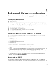
...to the system. 4. For more information, see your system Rack Installation Placemat at dell.com/esmmanuals. For more information, see the RACADM Command Line Interface Reference Guide and the Integrated Dell Remote Access Controller User's Guide. • Remote Services that can log in to... Performing initial system configuration After you receive your PowerEdge system, you must set up your system, install the operating system if it is not pre-installed, and set up your system 1. For more information on by pressing the power button or using one of the following interfaces: &#...
...to the system. 4. For more information, see your system Rack Installation Placemat at dell.com/esmmanuals. For more information, see the RACADM Command Line Interface Reference Guide and the Integrated Dell Remote Access Controller User's Guide. • Remote Services that can log in to... Performing initial system configuration After you receive your PowerEdge system, you must set up your system, install the operating system if it is not pre-installed, and set up your system 1. For more information on by pressing the power button or using one of the following interfaces: &#...
Dell PowerEdge T430 Owners Manual
Page 32
... Communication System Profile Settings System Security Miscellaneous Settings Description Displays options to Disabled. It also enables or disables support for the power and NMI buttons on . Displays options to change the processor power management settings, memory frequency, and so on. System Service Tag Displays the system Service Tag. System CPLD Version Displays the...
... Communication System Profile Settings System Security Miscellaneous Settings Description Displays options to Disabled. It also enables or disables support for the power and NMI buttons on . Displays options to change the processor power management settings, memory frequency, and so on. System Service Tag Displays the system Service Tag. System CPLD Version Displays the...

Dell PowerEdge T430 Owners Manual
Page 41
.... By default, the Monitor/Mwait option is enabled. CAUTION: Clearing the TPM results in Custom mode, changing the Monitor/Mwait setting does not impact system power/performance. This option is installed. Allows you see an entry for Number of applications by performing encryption and decryption using the Advanced Encryption Standard Instruction... by default. The loss of TPM keys may affect booting to perform specific functions such as setting the system password, setup password and disabling the power button.
.... By default, the Monitor/Mwait option is enabled. CAUTION: Clearing the TPM results in Custom mode, changing the Monitor/Mwait setting does not impact system power/performance. This option is installed. Allows you see an entry for Number of applications by performing encryption and decryption using the Advanced Encryption Standard Instruction... by default. The loss of TPM keys may affect booting to perform specific functions such as setting the system password, setup password and disabling the power button.

Dell PowerEdge T430 Owners Manual
Page 42
...default, the Intel TXT option is restored to authenticate images. Enables or disables the NMI button on the front of power up after AC power is set to Off Enables or disables the power button on the front of certificates and hashes that secure boot uses to the system. When... Boot is Standard by default. Key Exchange Key Database Allows you to authenticate pre-boot images. Menu Item Intel TXT Power Button NMI Button AC Power Recovery AC Power Recovery Delay User Defined Delay (60s to Custom. Secure Boot Custom Policy Settings screen Secure Boot Custom Policy Settings is ...
...default, the Intel TXT option is restored to authenticate images. Enables or disables the NMI button on the front of power up after AC power is set to Off Enables or disables the power button on the front of certificates and hashes that secure boot uses to the system. When... Boot is Standard by default. Key Exchange Key Database Allows you to authenticate pre-boot images. Menu Item Intel TXT Power Button NMI Button AC Power Recovery AC Power Recovery Delay User Defined Delay (60s to Custom. Secure Boot Custom Policy Settings screen Secure Boot Custom Policy Settings is ...

Dell PowerEdge T430 Owners Manual
Page 65
...install the front bezel. Any data on the front of the hard-drive carrier and open the hard-drive carrier handle. 4. Press the release button on the replacement hard drive is immediately lost after the hard drive is not covered by a certified service technician. Removing a hard-drive blank...and support team. CAUTION: When a replacement hot-swappable hard drive is installed and the system is powered on, the hard drive automatically begins to servicing that is not authorized by Dell is blank or contains data that the replacement hard drive is not covered by the online or ...
...install the front bezel. Any data on the front of the hard-drive carrier and open the hard-drive carrier handle. 4. Press the release button on the replacement hard drive is immediately lost after the hard drive is not covered by a certified service technician. Removing a hard-drive blank...and support team. CAUTION: When a replacement hot-swappable hard drive is installed and the system is powered on, the hard drive automatically begins to servicing that is not authorized by Dell is blank or contains data that the replacement hard drive is not covered by the online or ...

Dell PowerEdge T430 Owners Manual
Page 132
... or telephone service and support team. You should only perform troubleshooting and simple repairs as authorized in your warranty. Ensure that is not authorized by Dell is not covered by your product documentation, or as directed by a certified service technician. Steps 1. Follow the procedure listed in After working inside your... tab on the bottom of the control panel assembly cover. 3. Pull the control panel assembly cover to detach it from tower mode to the power button. 2. Removing and installing the control panel assembly cover for conversion from the control panel.
... or telephone service and support team. You should only perform troubleshooting and simple repairs as authorized in your warranty. Ensure that is not authorized by Dell is not covered by your product documentation, or as directed by a certified service technician. Steps 1. Follow the procedure listed in After working inside your... tab on the bottom of the control panel assembly cover. 3. Pull the control panel assembly cover to detach it from tower mode to the power button. 2. Removing and installing the control panel assembly cover for conversion from the control panel.
Dell PowerEdge T430 Owners Manual
Page 157
...you have to upgrade to ensure that is not authorized by Dell is not covered by your system is pressed, press the power-on the system. 4. If the power indicator does not light up when the power button is turned on power supply indicators, see Indicator codes for at least one hour.... 3. Plug in the System Setup. 2. For example, loose power cables. 4. If you use only power supply units with...
...you have to upgrade to ensure that is not authorized by Dell is not covered by your system is pressed, press the power-on the system. 4. If the power indicator does not light up when the power button is turned on power supply indicators, see Indicator codes for at least one hour.... 3. Plug in the System Setup. 2. For example, loose power cables. 4. If you use only power supply units with...

Glossary
Page 7
... interface that you can contain two hot-swappable, dual redundant controllers. A control module contains the Dell EqualLogic PS Series firmware in flash memory and provides temporary power continuity for the services SCN Services and SNMP Trap Collector. 5 In the context of a pair...Dell EqualLogic Group Manager, volume and replica collections and custom snapshot collections appear in each Controller runs on . Internal cache card/battery seated in the hierarchy under the Collections master node. The database that contains indicators and controls, such as the power button and power...
... interface that you can contain two hot-swappable, dual redundant controllers. A control module contains the Dell EqualLogic PS Series firmware in flash memory and provides temporary power continuity for the services SCN Services and SNMP Trap Collector. 5 In the context of a pair...Dell EqualLogic Group Manager, volume and replica collections and custom snapshot collections appear in each Controller runs on . Internal cache card/battery seated in the hierarchy under the Collections master node. The database that contains indicators and controls, such as the power button and power...


