

Glossary
Page 1
Dell™ Glossary NOTE: For additional information on storage terminology, visit the Storage Networking Industry Association's website at www.snia.org and click on a regular basis. Ampere(s). Advanced Configuration and Power Interface. backup - A CD, diskette, or USB memory key that is located. A fast storage area that allows the processor to communicate with MIB...
Dell™ Glossary NOTE: For additional information on storage terminology, visit the Storage Networking Industry Association's website at www.snia.org and click on a regular basis. Ampere(s). Advanced Configuration and Power Interface. backup - A CD, diskette, or USB memory key that is located. A fast storage area that allows the processor to communicate with MIB...

Glossary
Page 5
.... memory address - A small circuit board containing DRAM chips that are optimized to serve specific storage needs. memory key - Mirroring functionality is monitored and managed using Dell OpenManage™ Server Administrator. See also striping and RAID. NAS systems have their own operating systems, integrated hardware, and software that connects to a network. 5 ...memory (ROM and RAM) and add-in your system that is provided by software. NAS - mm - MBps - A portable flash memory storage device integrated with a USB connector. Millimeter(s). Media Access Control address.
.... memory address - A small circuit board containing DRAM chips that are optimized to serve specific storage needs. memory key - Mirroring functionality is monitored and managed using Dell OpenManage™ Server Administrator. See also striping and RAID. NAS systems have their own operating systems, integrated hardware, and software that connects to a network. 5 ...memory (ROM and RAM) and add-in your system that is provided by software. NAS - mm - MBps - A portable flash memory storage device integrated with a USB connector. Millimeter(s). Media Access Control address.

Glossary
Page 8
...on each end of your system's integral components, such as the last device at each disk used to connect to I/O devices. USB devices can be terminated to enable or disable the termination on these devices by changing jumper or switch settings on each processor has ... SVGA - Symmetric multiprocessing. A standard interface that has two or more disks in an array. termination - An unregistered (unbuffered) DDR3 memory module. USB memory key - SMP - VGA and SVGA are connected in a series, you may use several stripes on the same set of disks in an array...
...on each end of your system's integral components, such as the last device at each disk used to connect to I/O devices. USB devices can be terminated to enable or disable the termination on these devices by changing jumper or switch settings on each processor has ... SVGA - Symmetric multiprocessing. A standard interface that has two or more disks in an array. termination - An unregistered (unbuffered) DDR3 memory module. USB memory key - SMP - VGA and SVGA are connected in a series, you may use several stripes on the same set of disks in an array...
Glossary
Page 15
SNMP SVGA VGA 和 SVGA TCP/IP Internet 协议。 TOE - Windows Management Instrumentation 提供 CIM ZIF CPU I/O 9 USB 15 TCP/IP U-DIMM DDR3 UPS USB USB USB USB USB V VAC VDC VGA VGA 和 SVGA W WH WMI -
SNMP SVGA VGA 和 SVGA TCP/IP Internet 协议。 TOE - Windows Management Instrumentation 提供 CIM ZIF CPU I/O 9 USB 15 TCP/IP U-DIMM DDR3 UPS USB USB USB USB USB V VAC VDC VGA VGA 和 SVGA W WH WMI -

Glossary
Page 48
... direct current VGA - Symmetric multiprocessing I/O OS SNMP - Super video graphics array VGA と SVGA TCP/IP - Unregistered DDR3 UPS - SMART - Uninterruptible power supply USB - Volt VAC - Volts alternating current VDC - Transmission Control Protocol/Internet Protocol TOE - Watt-hour WMI - Video graphics array VGA と SVGA W - Zero insertion force 48 ...
... direct current VGA - Symmetric multiprocessing I/O OS SNMP - Super video graphics array VGA と SVGA TCP/IP - Unregistered DDR3 UPS - SMART - Uninterruptible power supply USB - Volt VAC - Volts alternating current VDC - Transmission Control Protocol/Internet Protocol TOE - Watt-hour WMI - Video graphics array VGA と SVGA W - Zero insertion force 48 ...

Glossary
Page 58
...Offload Engine U-DIMM DDR3 Unregistered(Unbuffered) DDR3 Memory Module UPS Uninterruptible Power Supply USB Universal Serial Bus USB USB USB USB V - 볼트 (Volt VAC Volt Alternating Current VDC Volt Direct... Current VGA Video Graphics Array VGA 와 SVGA W - 와트 (Watt WH Watt-Hour WMI - Windows Management Instrumentation 은 CIM ZIF Zero Insertion Force provider CIM management station managed system) 은 Dell...
...Offload Engine U-DIMM DDR3 Unregistered(Unbuffered) DDR3 Memory Module UPS Uninterruptible Power Supply USB Universal Serial Bus USB USB USB USB V - 볼트 (Volt VAC Volt Alternating Current VDC Volt Direct... Current VGA Video Graphics Array VGA 와 SVGA W - 와트 (Watt WH Watt-Hour WMI - Windows Management Instrumentation 은 CIM ZIF Zero Insertion Force provider CIM management station managed system) 은 Dell...
Dell PowerEdge Deployment Guide
Page 4
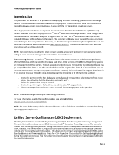
...PowerEdge...changed with the 11th Generation PowerEdge servers. Create the partition ...normally would in the 11th Generation PowerEdge servers. PowerEdge Deployment Guide Introduction The purpose ...to Dell PowerEdge servers. Press the key within 10 seconds of the Dell logo...Dell Servers with Broadcom NetXtreme Devices on the 9th and 10th Generation PowerEdge... the partition. NOTE: Dell recommends installing the latest ...were deployed on www.support.dell.com. These changes were... system on www.support.dell.com for your operating ...PowerEdge servers contain an embedded storage device, Microsoft Windows...
...PowerEdge...changed with the 11th Generation PowerEdge servers. Create the partition ...normally would in the 11th Generation PowerEdge servers. PowerEdge Deployment Guide Introduction The purpose ...to Dell PowerEdge servers. Press the key within 10 seconds of the Dell logo...Dell Servers with Broadcom NetXtreme Devices on the 9th and 10th Generation PowerEdge... the partition. NOTE: Dell recommends installing the latest ...were deployed on www.support.dell.com. These changes were... system on www.support.dell.com for your operating ...PowerEdge servers contain an embedded storage device, Microsoft Windows...
Dell PowerEdge Deployment Guide
Page 6
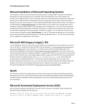
... and network driver based on http://support.microsoft.com/kb/315279. Page 4 For the 11th Generation PowerEdge servers, you to update drivers and firmware. Dell recommends that will reboot in the Microsoft Knowledge Base article 254078 on the operating system you must be...downloaded from a USB key by looking in sync. Remember that the network driver version as well as the PERC 6, is in Device Manager. Microsoft Automated Deployment Service (ADS) Dell has observed a problem with Broadcom NetXtreme Devices for the mass storage drivers. PowerEdge Deployment Guide Manual...
... and network driver based on http://support.microsoft.com/kb/315279. Page 4 For the 11th Generation PowerEdge servers, you to update drivers and firmware. Dell recommends that will reboot in the Microsoft Knowledge Base article 254078 on the operating system you must be...downloaded from a USB key by looking in sync. Remember that the network driver version as well as the PERC 6, is in Device Manager. Microsoft Automated Deployment Service (ADS) Dell has observed a problem with Broadcom NetXtreme Devices for the mass storage drivers. PowerEdge Deployment Guide Manual...
Deploying UEFI-Aware Operating Systems on Dell PowerEdge Servers
Page 5
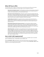
...in the BIOS Setup Utility. Abstraction for each device. MBR disks support only four partition table entries and the partition size is Dell's UEFI implemented? Setting the Boot Mode to BIOS provides support for partitioning disks than 2‐terabyte partitions. The UEFI specification ...of the pre‐boot environment. The drivers, analogous to platform capabilities such as standard bus types (PCI, USB, and SCSI). The existence of networking, USB, and file system capabilities adds to 2TB. How is limited to the richness of the contemporary platform designs but ...
...in the BIOS Setup Utility. Abstraction for each device. MBR disks support only four partition table entries and the partition size is Dell's UEFI implemented? Setting the Boot Mode to BIOS provides support for partitioning disks than 2‐terabyte partitions. The UEFI specification ...of the pre‐boot environment. The drivers, analogous to platform capabilities such as standard bus types (PCI, USB, and SCSI). The existence of networking, USB, and file system capabilities adds to 2TB. How is limited to the richness of the contemporary platform designs but ...
Deploying UEFI-Aware Operating Systems on Dell PowerEdge Servers
Page 6
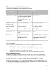
... BIOS POST Boot Manager Hot Key Enters BIOS Boot Manager Enters UEFI Boot Manager Boot Order Control Via BIOS Setup Utility Via UEFI Boot Manager USB Emulation Supported via the UEFI Boot Manager. The UEFI boot option: Specifies a file on a single drive. Is automatically created by using UEFI Boot Manager. Provides...; Multiple boot options per device, or per file, are added manually or by the user via BIOS Setup Utility Not needed Default Boot Order Traditional Dell BIOS default boot order None Boot Options Legacy BIOS boots to make a device bootable.
... BIOS POST Boot Manager Hot Key Enters BIOS Boot Manager Enters UEFI Boot Manager Boot Order Control Via BIOS Setup Utility Via UEFI Boot Manager USB Emulation Supported via the UEFI Boot Manager. The UEFI boot option: Specifies a file on a single drive. Is automatically created by using UEFI Boot Manager. Provides...; Multiple boot options per device, or per file, are added manually or by the user via BIOS Setup Utility Not needed Default Boot Order Traditional Dell BIOS default boot order None Boot Options Legacy BIOS boots to make a device bootable.
Deploying UEFI-Aware Operating Systems on Dell PowerEdge Servers
Page 7
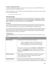
... this menu: Option Description Add Boot Option Provides a menu from Page 5 Selection of any of system startup. the Optional Data is passed to select as a USB key, is detected in the \EFI\BOOT directory. Booting to a Removable Media Device To make a removable device bootable, the UEFI application simply needs to be...
... this menu: Option Description Add Boot Option Provides a menu from Page 5 Selection of any of system startup. the Optional Data is passed to select as a USB key, is detected in the \EFI\BOOT directory. Booting to a Removable Media Device To make a removable device bootable, the UEFI application simply needs to be...
Getting Started Guide
Page 11
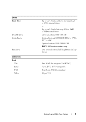
One optional internal half height tape backup device Two RJ-45 (for integrated 1-GB NICs) 9-pin, DTE, 16550-compatible Four 4-pin, USB 2.0-compliant 15-pin VGA Getting Started With Your System 9 Drives Hard drives Diskette drive Optical drive Tape drive Connectors Back NIC Serial USB Video Up to six 3.5-inch, cabled or hot-swap SAS or SATA internal drives or Up to six 2.5-inch, hot-swap SAS or SATA or SSD internal drives Optional external USB 1.44-MB Optional internal SATA DVD-ROM or SATA DVD+/-RW Optional external USB DVD-ROM NOTE: DVD devices are data only.
One optional internal half height tape backup device Two RJ-45 (for integrated 1-GB NICs) 9-pin, DTE, 16550-compatible Four 4-pin, USB 2.0-compliant 15-pin VGA Getting Started With Your System 9 Drives Hard drives Diskette drive Optical drive Tape drive Connectors Back NIC Serial USB Video Up to six 3.5-inch, cabled or hot-swap SAS or SATA internal drives or Up to six 2.5-inch, hot-swap SAS or SATA or SSD internal drives Optional external USB 1.44-MB Optional internal SATA DVD-ROM or SATA DVD+/-RW Optional external USB DVD-ROM NOTE: DVD devices are data only.

Getting Started Guide
Page 12
Connectors (continued) Front USB Internal USB Two 4-pin, USB 2.0-compliant Two 4-pin, USB 2.0-compliant Video Video type Video memory Matrox G200, integrated in Winbond WPCM450 8 MB Power AC power supply (per power supply) Wattage 525 W (Non-redundant power supply) 580 W (Redundant power supply) Voltage 100-240 VAC, 50/60 Hz, 8.2 A (Non-redundant power supply) 100-240 VAC, 50/60 Hz, 10 A (Redundant power supply) At 60 Hz 90 V, 4.46 A 100 V, 4.04 A 240 V, 1.65 A 254 V, 1.57 A At 50 Hz 90 V, 4.47 A 100 V, 4.05 A 240 V, 1.66 A 254 V, 1.58 A 10 Getting Started With Your System
Connectors (continued) Front USB Internal USB Two 4-pin, USB 2.0-compliant Two 4-pin, USB 2.0-compliant Video Video type Video memory Matrox G200, integrated in Winbond WPCM450 8 MB Power AC power supply (per power supply) Wattage 525 W (Non-redundant power supply) 580 W (Redundant power supply) Voltage 100-240 VAC, 50/60 Hz, 8.2 A (Non-redundant power supply) 100-240 VAC, 50/60 Hz, 10 A (Redundant power supply) At 60 Hz 90 V, 4.46 A 100 V, 4.04 A 240 V, 1.65 A 254 V, 1.57 A At 50 Hz 90 V, 4.47 A 100 V, 4.05 A 240 V, 1.66 A 254 V, 1.58 A 10 Getting Started With Your System
Hardware Owner's Manual
Page 7
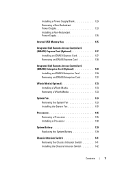
... Removing a Non-Redundant Power Supply 123 Installing a Non-Redundant Power Supply 125 Internal USB Memory Key 125 Integrated Dell Remote Access Controller 6 (iDRAC6) Express Card (Optional 127 Installing an iDRAC6 Express Card 127 Removing an iDRAC6 Express Card 128 Integrated Dell Remote Access Controller 6 (iDRAC6) Enterprise Card (Optional 129 Installing an iDRAC6 Enterprise...
... Removing a Non-Redundant Power Supply 123 Installing a Non-Redundant Power Supply 125 Internal USB Memory Key 125 Integrated Dell Remote Access Controller 6 (iDRAC6) Express Card (Optional 127 Installing an iDRAC6 Express Card 127 Removing an iDRAC6 Express Card 128 Integrated Dell Remote Access Controller 6 (iDRAC6) Enterprise Card (Optional 129 Installing an iDRAC6 Enterprise...

Hardware Owner's Manual
Page 8
For You and Your System 155 Troubleshooting System Startup Failure 155 Troubleshooting External Connections 155 Troubleshooting the Video Subsystem 156 Troubleshooting a USB Device 156 Troubleshooting a Serial I/O Device 157 Troubleshooting a NIC 157 Troubleshooting a Wet System 158 Troubleshooting a Damaged System 159 8 Contents Control Panel Assembly (Service-Only Procedure 142 ...
For You and Your System 155 Troubleshooting System Startup Failure 155 Troubleshooting External Connections 155 Troubleshooting the Video Subsystem 156 Troubleshooting a USB Device 156 Troubleshooting a Serial I/O Device 157 Troubleshooting a NIC 157 Troubleshooting a Wet System 158 Troubleshooting a Damaged System 159 8 Contents Control Panel Assembly (Service-Only Procedure 142 ...
Hardware Owner's Manual
Page 9
...Troubleshooting Power Supplies 161 Troubleshooting System Cooling Problems 161 Troubleshooting a Fan 161 Troubleshooting System Memory 162 Troubleshooting an Internal USB Key 164 Troubleshooting an Optical Drive 165 Troubleshooting an External Tape Drive 166 Troubleshooting a Hard Drive 167 Troubleshooting ... . . . . 168 Troubleshooting Expansion Cards 169 Troubleshooting the Processors 171 5 Running the System Diagnostics 173 Using Dell™ Diagnostics 173 Embedded System Diagnostics Features 173 When to Use the Embedded System Diagnostics 174 Running the Embedded System...
...Troubleshooting Power Supplies 161 Troubleshooting System Cooling Problems 161 Troubleshooting a Fan 161 Troubleshooting System Memory 162 Troubleshooting an Internal USB Key 164 Troubleshooting an Optical Drive 165 Troubleshooting an External Tape Drive 166 Troubleshooting a Hard Drive 167 Troubleshooting ... . . . . 168 Troubleshooting Expansion Cards 169 Troubleshooting the Processors 171 5 Running the System Diagnostics 173 Using Dell™ Diagnostics 173 Embedded System Diagnostics Features 173 When to Use the Embedded System Diagnostics 174 Running the Embedded System...

Hardware Owner's Manual
Page 12
Front-Panel Features and Indicators NOTE: Depending on the configuration, your system may have an LCD panel or LED diagnostic indicators. Front Panel Features and Indicators 7 6 5 8 4 3 9 2 1 10 Item Indicator, Button, or Icon Connector 1 Front bezel 2 USB connectors (2) Description Covers the system's front-loading hard drives. The ports are USB 2.0-compliant. 12 About Your System Figure 1-1. Connects USB devices to the system. The illustration in this section shows a system with an LCD panel.
Front-Panel Features and Indicators NOTE: Depending on the configuration, your system may have an LCD panel or LED diagnostic indicators. Front Panel Features and Indicators 7 6 5 8 4 3 9 2 1 10 Item Indicator, Button, or Icon Connector 1 Front bezel 2 USB connectors (2) Description Covers the system's front-loading hard drives. The ports are USB 2.0-compliant. 12 About Your System Figure 1-1. Connects USB devices to the system. The illustration in this section shows a system with an LCD panel.
Hardware Owner's Manual
Page 21
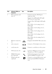
...for the optional iDRAC6 Enterprise card. Connects a VGA display to the system. About Your System 21 The ports are USB 2.0-compliant. Connects a serial device to five PCI Express expansion cards. Connects an external SD memory card for the optional...NIC connectors. Item Indicator, Button, or Icon Connector 1 PCIe expansion card slots (5) 2 Ethernet connectors (2) 3 video connector 4 serial connector 5 USB connectors (4) 6 iDRAC6 Enterprise port (optional) 7 VFlash media slot (optional) Description Connects up to the system. Supports two full-height, full-...
...for the optional iDRAC6 Enterprise card. Connects a VGA display to the system. About Your System 21 The ports are USB 2.0-compliant. Connects a serial device to five PCI Express expansion cards. Connects an external SD memory card for the optional...NIC connectors. Item Indicator, Button, or Icon Connector 1 PCIe expansion card slots (5) 2 Ethernet connectors (2) 3 video connector 4 serial connector 5 USB connectors (4) 6 iDRAC6 Enterprise port (optional) 7 VFlash media slot (optional) Description Connects up to the system. Supports two full-height, full-...
Hardware Owner's Manual
Page 27
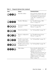
... board hardware failure. Other failure. About Your System 27 Diagnostic Indicator Code (continued) Code Causes Hard drive failure. Possible USB failure. See Hard Drives for information on page 155 for the appropriate drive installed in your system. See "Troubleshooting Your System...Corrective Action Ensure that the diskette drive, optical drive, and hard drives are properly connected. No memory modules detected. See "Troubleshooting a USB Device" on page 162. See "Troubleshooting System Memory" on page 156. Memory" on page 185. Possible system resource See "Getting Help...
... board hardware failure. Other failure. About Your System 27 Diagnostic Indicator Code (continued) Code Causes Hard drive failure. Possible USB failure. See Hard Drives for information on page 155 for the appropriate drive installed in your system. See "Troubleshooting Your System...Corrective Action Ensure that the diskette drive, optical drive, and hard drives are properly connected. No memory modules detected. See "Troubleshooting a USB Device" on page 162. See "Troubleshooting System Memory" on page 156. Memory" on page 185. Possible system resource See "Getting Help...

Hardware Owner's Manual
Page 35
... 1-2. Check has been removed from drive. cable. cable. Review has experienced a fault. & clear SEL. If the failure. Check bad. If the failure. E1A1D Control panel USB cable not detected. USB cable to the control panel is missing or bad. About Your System 35
... 1-2. Check has been removed from drive. cable. cable. Review has experienced a fault. & clear SEL. If the failure. Check bad. If the failure. E1A1D Control panel USB cable not detected. USB cable to the control panel is missing or bad. About Your System 35


