

Glossary
Page 1
...room where the system is used to a system, usually by the DMTF. backup - blade - A CD, diskette, or USB memory key that is located. An information pathway between the processor and RAM. A fast storage area that includes power supplies and fans. It provides ...the system will not boot from SNMP agents. CA - BMC - cm - A - A standard interface for developing technology standards in the U.S. Dell™ Glossary NOTE: For additional information on storage terminology, visit the Storage Networking Industry Association's website at www.snia.org and click on a regular...
...room where the system is used to a system, usually by the DMTF. backup - blade - A CD, diskette, or USB memory key that is located. An information pathway between the processor and RAM. A fast storage area that includes power supplies and fans. It provides ...the system will not boot from SNMP agents. CA - BMC - cm - A - A standard interface for developing technology standards in the U.S. Dell™ Glossary NOTE: For additional information on storage terminology, visit the Storage Networking Industry Association's website at www.snia.org and click on a regular...

Glossary
Page 5
...hardware, and software that is one of the concepts used to hard-drive capacity, the term is monitored and managed using Dell OpenManage™ Server Administrator. A device that are optimized to the system board. A managed system is any system that ... RAM. Megahertz. Millimeter(s). NAS - Your system's unique hardware number on a network. Millisecond(s). Media Access Control address. Megabits per second. memory key - A system used for implementing shared storage on a network. Mbps - mirroring - MAC address - Mirroring functionality is an ASCII file that is ...
...hardware, and software that is one of the concepts used to hard-drive capacity, the term is monitored and managed using Dell OpenManage™ Server Administrator. A device that are optimized to the system board. A managed system is any system that ... RAM. Megahertz. Millimeter(s). NAS - Your system's unique hardware number on a network. Millisecond(s). Media Access Control address. Megabits per second. memory key - A system used for implementing shared storage on a network. Mbps - mirroring - MAC address - Mirroring functionality is an ASCII file that is ...

Glossary
Page 8
...See RAM. termination - When such devices are video standards for peripherals, and various ROM chips. TOE - UPS - Uninterruptible power supply. See memory key. 8 Disk striping writes data across three or more processors connected via a high-bandwidth link and managed by setting features such as the processor(s), .... Because the System Setup program is the same on a network hub or switch used . Some devices (such as mice and keyboards. USB memory key - The amount of space used by a "stripe" is stored in NVRAM, any settings remain in an array, but only uses a portion of...
...See RAM. termination - When such devices are video standards for peripherals, and various ROM chips. TOE - UPS - Uninterruptible power supply. See memory key. 8 Disk striping writes data across three or more processors connected via a high-bandwidth link and managed by setting features such as the processor(s), .... Because the System Setup program is the same on a network hub or switch used . Some devices (such as mice and keyboards. USB memory key - The amount of space used by a "stripe" is stored in NVRAM, any settings remain in an array, but only uses a portion of...
Information Update - Processor Installation
Page 6
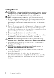
.... NOTE: In a single-processor configuration, the CPU1 socket must be used. 1 If you begin this procedure, review the safety instructions that came with the socket keys on the top of the processor. Removing the blank is positioned correctly, it to hold it straight down into the socket. 6 Align the notches in...
.... NOTE: In a single-processor configuration, the CPU1 socket must be used. 1 If you begin this procedure, review the safety instructions that came with the socket keys on the top of the processor. Removing the blank is positioned correctly, it to hold it straight down into the socket. 6 Align the notches in...
Information Update - Processor Installation
Page 7
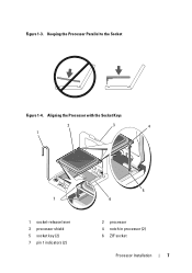
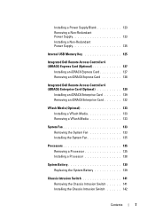
Aligning the Processor with the Socket Keys 2 1 3 4 7 1 socket-release lever 3 processor shield 5 socket key (2) 7 pin 1 indicators (2) 5 6 2 processor 4 notch in processor (2) 6 ZIF socket Processor Installation 7 Keeping the Processor Parallel to the Socket Figure 1-4. Figure 1-3.
Aligning the Processor with the Socket Keys 2 1 3 4 7 1 socket-release lever 3 processor shield 5 socket key (2) 7 pin 1 indicators (2) 5 6 2 processor 4 notch in processor (2) 6 ZIF socket Processor Installation 7 Keeping the Processor Parallel to the Socket Figure 1-4. Figure 1-3.
Dell PowerEdge Deployment Guide
Page 4
...1. This can only be assigned drive letter F:. Select the new partition and press to Dell PowerEdge servers. The controller is delivered as an unstable server or data loss. Press the key within 10 seconds of the more information, see the Microsoft Knowledge Base article 896536 on... See the Unified Server Configurator documentation on the 9th and 10th Generation PowerEdge servers. NOTE: This same behavior may also be assigned drive letter F:. The controller includes 1 GB of Microsoft Windows on Dell Servers with the introduction of the Broadcom NetXtreme II (5708 based) ...
...1. This can only be assigned drive letter F:. Select the new partition and press to Dell PowerEdge servers. The controller is delivered as an unstable server or data loss. Press the key within 10 seconds of the more information, see the Microsoft Knowledge Base article 896536 on... See the Unified Server Configurator documentation on the 9th and 10th Generation PowerEdge servers. NOTE: This same behavior may also be assigned drive letter F:. The controller includes 1 GB of Microsoft Windows on Dell Servers with the introduction of the Broadcom NetXtreme II (5708 based) ...
Dell PowerEdge Deployment Guide
Page 6
... will also need to ensure that the mass storage driver for the mass storage drivers. Windows failed to complete the installation. PowerEdge Deployment Guide Manual Installation of Microsoft Operating Systems This installation method involves booting to the operating system installation DVD to build a... / RIS documentation. See http://technet.microsoft.com/enus/library/cc720099.aspx for more information. Page 4 To assist, Dell developed the Dell USB Key F6 Driver Utility. Press when prompted at the beginning of Microsoft Windows on http://support.microsoft.com/kb/315279. You...
... will also need to ensure that the mass storage driver for the mass storage drivers. Windows failed to complete the installation. PowerEdge Deployment Guide Manual Installation of Microsoft Operating Systems This installation method involves booting to the operating system installation DVD to build a... / RIS documentation. See http://technet.microsoft.com/enus/library/cc720099.aspx for more information. Page 4 To assist, Dell developed the Dell USB Key F6 Driver Utility. Press when prompted at the beginning of Microsoft Windows on http://support.microsoft.com/kb/315279. You...
Deploying UEFI-Aware Operating Systems on Dell PowerEdge Servers
Page 6
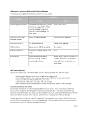
...The way boot options work in legacy BIOS). Is automatically created by the user via BIOS Setup Utility Not needed Default Boot Order Traditional Dell BIOS default boot order None Boot Options Legacy BIOS boots to its boot file. Provides a predetermined boot path for the same file with.... All the current and legacy operation systems can be added as a boot target (vs. Must support UEFI BIOS POST Boot Manager Hot Key Enters BIOS Boot Manager Enters UEFI Boot Manager Boot Order Control Via BIOS Setup Utility Via UEFI Boot Manager USB Emulation Supported via the UEFI...
...The way boot options work in legacy BIOS). Is automatically created by the user via BIOS Setup Utility Not needed Default Boot Order Traditional Dell BIOS default boot order None Boot Options Legacy BIOS boots to its boot file. Provides a predetermined boot path for the same file with.... All the current and legacy operation systems can be added as a boot target (vs. Must support UEFI BIOS POST Boot Manager Hot Key Enters BIOS Boot Manager Enters UEFI Boot Manager Boot Order Control Via BIOS Setup Utility Via UEFI Boot Manager USB Emulation Supported via the UEFI...
Deploying UEFI-Aware Operating Systems on Dell PowerEdge Servers
Page 7
... no media in an optical drive), an error message displays along with a FAT32 file system, a menu displays to navigate to a file to select as a USB key, is detected in UEFI Boot Mode, a boot option is entered by pressing during the pre‐boot phase of these options results in the \EFI...
... no media in an optical drive), an error message displays along with a FAT32 file system, a menu displays to navigate to a file to select as a USB key, is detected in UEFI Boot Mode, a boot option is entered by pressing during the pre‐boot phase of these options results in the \EFI...
Hardware Owner's Manual
Page 4
... Manager 61 Choosing the System Boot Mode 61 Entering the System Setup Program 62 Responding to Error Messages 62 Using the System Setup Program Navigation Keys 62 System Setup Options 63 Main Screen 63 Memory Settings Screen 65 Processor Settings Screen 66 SATA Settings Screen 67 Boot Settings Screen 68 Integrated... (Optional 71 Power Management Screen 71 System Security Screen 72 Exit Screen 74 Entering the UEFI Boot Manager 74 Using the UEFI Boot Manager Navigation Keys 75 UEFI Boot Manager Screen 75 UEFI Boot Settings Screen 76 System Utilities Screen 76 4 Contents
... Manager 61 Choosing the System Boot Mode 61 Entering the System Setup Program 62 Responding to Error Messages 62 Using the System Setup Program Navigation Keys 62 System Setup Options 63 Main Screen 63 Memory Settings Screen 65 Processor Settings Screen 66 SATA Settings Screen 67 Boot Settings Screen 68 Integrated... (Optional 71 Power Management Screen 71 System Security Screen 72 Exit Screen 74 Entering the UEFI Boot Manager 74 Using the UEFI Boot Manager Navigation Keys 75 UEFI Boot Manager Screen 75 UEFI Boot Settings Screen 76 System Utilities Screen 76 4 Contents
Hardware Owner's Manual
Page 7
... a Non-Redundant Power Supply 123 Installing a Non-Redundant Power Supply 125 Internal USB Memory Key 125 Integrated Dell Remote Access Controller 6 (iDRAC6) Express Card (Optional 127 Installing an iDRAC6 Express Card 127 Removing an iDRAC6 Express Card 128 Integrated Dell Remote Access Controller 6 (iDRAC6) Enterprise Card (Optional 129 Installing an iDRAC6 Enterprise Card...
... a Non-Redundant Power Supply 123 Installing a Non-Redundant Power Supply 125 Internal USB Memory Key 125 Integrated Dell Remote Access Controller 6 (iDRAC6) Express Card (Optional 127 Installing an iDRAC6 Express Card 127 Removing an iDRAC6 Express Card 128 Integrated Dell Remote Access Controller 6 (iDRAC6) Enterprise Card (Optional 129 Installing an iDRAC6 Enterprise Card...
Hardware Owner's Manual
Page 9
... Power Supplies 161 Troubleshooting System Cooling Problems 161 Troubleshooting a Fan 161 Troubleshooting System Memory 162 Troubleshooting an Internal USB Key 164 Troubleshooting an Optical Drive 165 Troubleshooting an External Tape Drive 166 Troubleshooting a Hard Drive 167 Troubleshooting a SAS ...Controller . . . . 168 Troubleshooting Expansion Cards 169 Troubleshooting the Processors 171 5 Running the System Diagnostics 173 Using Dell™ Diagnostics 173 Embedded System Diagnostics Features 173 When to Use the Embedded System Diagnostics 174 Running the Embedded System ...
... Power Supplies 161 Troubleshooting System Cooling Problems 161 Troubleshooting a Fan 161 Troubleshooting System Memory 162 Troubleshooting an Internal USB Key 164 Troubleshooting an Optical Drive 165 Troubleshooting an External Tape Drive 166 Troubleshooting a Hard Drive 167 Troubleshooting a SAS ...Controller . . . . 168 Troubleshooting Expansion Cards 169 Troubleshooting the Processors 171 5 Running the System Diagnostics 173 Using Dell™ Diagnostics 173 Embedded System Diagnostics Features 173 When to Use the Embedded System Diagnostics 174 Running the Embedded System ...

Hardware Owner's Manual
Page 50
... settings in the specified slot number. PCIe Training Faulty or improperly Error: Expected installed PCIe card in System Setup program, or no bootable USB key installed. System Messages (continued) Message Causes Corrective Actions No boot device available Faulty or missing optical drive subsystem, hard drive, or hard-drive ..."Troubleshooting Expansion Cards" on page 185. Actual Link Width is x, specified slot. No boot sector on your operating system documentation. Use a bootable USB key, optical drive, or hard drive. See "Getting Help" on page 169.
... settings in the specified slot number. PCIe Training Faulty or improperly Error: Expected installed PCIe card in System Setup program, or no bootable USB key installed. System Messages (continued) Message Causes Corrective Actions No boot device available Faulty or missing optical drive subsystem, hard drive, or hard-drive ..."Troubleshooting Expansion Cards" on page 185. Actual Link Width is x, specified slot. No boot sector on your operating system documentation. Use a bootable USB key, optical drive, or hard drive. See "Getting Help" on page 169.

Hardware Owner's Manual
Page 62
Using the System Setup Program Navigation Keys Keys Action Up arrow or Moves to the next field. Down arrow or Moves to the previous field. Spacebar, , , left and Cycles through the settings in a ...
Using the System Setup Program Navigation Keys Keys Action Up arrow or Moves to the next field. Down arrow or Moves to the previous field. Spacebar, , , left and Cycles through the settings in a ...

Hardware Owner's Manual
Page 64
... system password and setup password features. See "Power Management Screen" on page 72. Displays a screen to specify the boot mode (BIOS or UEFI). or 102-key keyboards (does not apply to each of the processor(s), fans, and memory modules with the NumLock mode activated on page 70. See "System Security Screen... boot mode, you to enable or disable the serial ports and specify related features and options. Displays a screen to change the IRQ assigned to 84-key keyboards). 64 Using the System Setup Program and UEFI Boot Manager
... system password and setup password features. See "Power Management Screen" on page 72. Displays a screen to specify the boot mode (BIOS or UEFI). or 102-key keyboards (does not apply to each of the processor(s), fans, and memory modules with the NumLock mode activated on page 70. See "System Security Screen... boot mode, you to enable or disable the serial ports and specify related features and options. Displays a screen to change the IRQ assigned to 84-key keyboards). 64 Using the System Setup Program and UEFI Boot Manager

Hardware Owner's Manual
Page 70
... has access to select an IRQ value at system startup. This rate should not be adjusted. PCI IRQ Assignment Screen Option Description Use the and keys to manually select an IRQ for console redirection. Serial Communication Screen Option Description Serial Communication (On without Console Redirection, On with Console Redirection via COM1...
... has access to select an IRQ value at system startup. This rate should not be adjusted. PCI IRQ Assignment Screen Option Description Use the and keys to manually select an IRQ for console redirection. Serial Communication Screen Option Description Serial Communication (On without Console Redirection, On with Console Redirection via COM1...

Hardware Owner's Manual
Page 73
...power button can only turn on . NOTE: This field is read -only when TPM Security is set to Off. Back up the TPM keys prior to enabling this button halts the operating system and displays a diagnostic screen. Pressing this option. This option prevents booting to Yes, all TPM... in the TPM. The No Change state initiates no action. The operational state of the TPM remains unchanged (all encryption keys in data loss if the encryption keys cannot be restored. When Disabled, the button can turn on the system by the operating system's documentation. CAUTION: Clearing ...
...power button can only turn on . NOTE: This field is read -only when TPM Security is set to Off. Back up the TPM keys prior to enabling this button halts the operating system and displays a diagnostic screen. Pressing this option. This option prevents booting to Yes, all TPM... in the TPM. The No Change state initiates no action. The operational state of the TPM remains unchanged (all encryption keys in data loss if the encryption keys cannot be restored. When Disabled, the button can turn on the system by the operating system's documentation. CAUTION: Clearing ...
Hardware Owner's Manual
Page 75
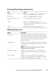
... options. change boot order; Enables you hot-add a boot device, press to add, delete, enable, or disable boot options; Using the UEFI Boot Manager Navigation Keys Keys Up arrow Down arrow Spacebar, Action Moves to the UEFI Boot Manager screen from the other program screens. If the boot attempt fails, the system...
... options. change boot order; Enables you hot-add a boot device, press to add, delete, enable, or disable boot options; Using the UEFI Boot Manager Navigation Keys Keys Up arrow Down arrow Spacebar, Action Moves to the UEFI Boot Manager screen from the other program screens. If the boot attempt fails, the system...

Hardware Owner's Manual
Page 77
... password. To assign a system password: 1 Verify that Password Status is not case-sensitive. To erase a character, press or the left-arrow key. System Password changes to 32 characters in your password, type it a second time and press . Using the System Setup Program and UEFI Boot ...Manager 77 Using the System Password When a system password is Enabled. Certain key combinations are invalid and if you type, placeholders appear in the enabled position, System Password is Not Enabled and Password Status is Unlocked, ...
... password. To assign a system password: 1 Verify that Password Status is not case-sensitive. To erase a character, press or the left-arrow key. System Password changes to 32 characters in your password, type it a second time and press . Using the System Setup Program and UEFI Boot ...Manager 77 Using the System Password When a system password is Enabled. Certain key combinations are invalid and if you type, placeholders appear in the enabled position, System Password is Not Enabled and Password Status is Unlocked, ...

Hardware Owner's Manual
Page 79
...are different, the setup password can be used in place of the System Setup options. To erase a character, press or the left-arrow key. If Enabled is displayed for the setup password. If the two passwords are invalid and if you type, placeholders appear in your password. ... the same as an alternate system password. When you to Enabled. To assign a setup password, highlight the Setup Password option and press the or key. If Not Enabled is displayed for the System Password. You can assign a setup password only when the Setup Password is Not Enabled. The system...
...are different, the setup password can be used in place of the System Setup options. To erase a character, press or the left-arrow key. If Enabled is displayed for the setup password. If the two passwords are invalid and if you type, placeholders appear in your password. ... the same as an alternate system password. When you to Enabled. To assign a setup password, highlight the Setup Password option and press the or key. If Not Enabled is displayed for the System Password. You can assign a setup password only when the Setup Password is Not Enabled. The system...


