

Glossary
Page 8
...configuration information - When such devices are video standards for multiple USB-compliant devices, such as password protection. Super video graphics array. termination - TCP/IP offload engine. A port on each disk used to connect to your system's integral ... power to other hubs or switches without requiring a crossover cable. Transmission Control Protocol/Internet Protocol. TOE - uplink port - TCP/IP - A USB connector provides a single connection point for video adapters with greater resolution and color display capabilities than previous standards. Symmetric...
...configuration information - When such devices are video standards for multiple USB-compliant devices, such as password protection. Super video graphics array. termination - TCP/IP offload engine. A port on each disk used to connect to your system's integral ... power to other hubs or switches without requiring a crossover cable. Transmission Control Protocol/Internet Protocol. TOE - uplink port - TCP/IP - A USB connector provides a single connection point for video adapters with greater resolution and color display capabilities than previous standards. Symmetric...

Hardware Owner's Manual
Page 12
Front Panel Features and Indicators 7 6 5 8 4 3 9 2 1 10 Item Indicator, Button, or Icon Connector 1 Front bezel 2 USB connectors (2) Description Covers the system's front-loading hard drives. Figure 1-1. The ports are USB 2.0-compliant. 12 About Your System Front-Panel Features and Indicators NOTE: Depending on the configuration, your system may have an LCD panel or LED diagnostic indicators. Connects USB devices to the system. The illustration in this section shows a system with an LCD panel.
Front Panel Features and Indicators 7 6 5 8 4 3 9 2 1 10 Item Indicator, Button, or Icon Connector 1 Front bezel 2 USB connectors (2) Description Covers the system's front-loading hard drives. Figure 1-1. The ports are USB 2.0-compliant. 12 About Your System Front-Panel Features and Indicators NOTE: Depending on the configuration, your system may have an LCD panel or LED diagnostic indicators. Connects USB devices to the system. The illustration in this section shows a system with an LCD panel.
Hardware Owner's Manual
Page 21
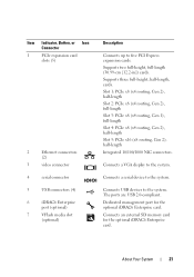
...card. Item Indicator, Button, or Icon Connector 1 PCIe expansion card slots (5) 2 Ethernet connectors (2) 3 video connector 4 serial connector 5 USB connectors (4) 6 iDRAC6 Enterprise port (optional) 7 VFlash media slot (optional) Description Connects up to the system. Connects an external SD memory card for the optional iDRAC6 ...Enterprise card. Connects a VGA display to five PCI Express expansion cards. The ports are USB 2.0-compliant. About Your System 21 Supports two full-height, full-length (30.99-cm [12.2-in]) cards. Connects...
...card. Item Indicator, Button, or Icon Connector 1 PCIe expansion card slots (5) 2 Ethernet connectors (2) 3 video connector 4 serial connector 5 USB connectors (4) 6 iDRAC6 Enterprise port (optional) 7 VFlash media slot (optional) Description Connects up to the system. Connects an external SD memory card for the optional iDRAC6 ...Enterprise card. Connects a VGA display to five PCI Express expansion cards. The ports are USB 2.0-compliant. About Your System 21 Supports two full-height, full-length (30.99-cm [12.2-in]) cards. Connects...

Hardware Owner's Manual
Page 48
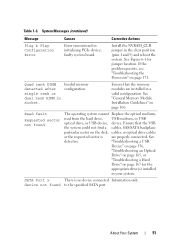
... installed in manufacturing Reboot to enable the USB port(s). Manufacturing mode detected System is physically available. See "Entering the System Setup Program" on page 106. The following DIMM has been disabled: x Invalid memory ...program to take the system mode. Ensure that the memory configuration. page 185. Memory Initialization Warning: Memory size may not work because all user accessible USB ports are installed in the system BIOS. out of manufacturing mode. The system will run but with the specified memory module disabled. System Messages (continued) ...
... installed in manufacturing Reboot to enable the USB port(s). Manufacturing mode detected System is physically available. See "Entering the System Setup Program" on page 106. The following DIMM has been disabled: x Invalid memory ...program to take the system mode. Ensure that the memory configuration. page 185. Memory Initialization Warning: Memory size may not work because all user accessible USB ports are installed in the system BIOS. out of manufacturing mode. The system will run but with the specified memory module disabled. System Messages (continued) ...
Hardware Owner's Manual
Page 51
...in socket. single rank or dual rank DIMM in the clear position (pins 1 and 3) and reboot the system. Ensure that the USB the system could not find a cables, SAS/SATA backplane particular sector on page 106. device not found The operating system cannot Replace ... that the memory modules are properly connected. Read fault Requested sector not found to the specified SATA port. See Figure 6-1 for the appropriate drive(s) installed in your system. SATA Port x There is are installed in initializing PCIe device; About Your System 51 See "General Memory Module...
...in socket. single rank or dual rank DIMM in the clear position (pins 1 and 3) and reboot the system. Ensure that the USB the system could not find a cables, SAS/SATA backplane particular sector on page 106. device not found The operating system cannot Replace ... that the memory modules are properly connected. Read fault Requested sector not found to the specified SATA port. See Figure 6-1 for the appropriate drive(s) installed in your system. SATA Port x There is are installed in initializing PCIe device; About Your System 51 See "General Memory Module...
Hardware Owner's Manual
Page 69
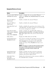
... systems that support WDAT implementations of the Advanced Configuration and Power Interface (ACPI) 3.0b specification. Internal USB Port 1 (On default) Enables or disables the internal USB port. Integrated Devices Screen Option Description User Accessible USB Ports Enables or disables the user accessible USB ports. (All Ports On default) Options are Enabled, Enabled with PXE, and Enabled with PXE; Internal...
... systems that support WDAT implementations of the Advanced Configuration and Power Interface (ACPI) 3.0b specification. Internal USB Port 1 (On default) Enables or disables the internal USB port. Integrated Devices Screen Option Description User Accessible USB Ports Enables or disables the user accessible USB ports. (All Ports On default) Options are Enabled, Enabled with PXE, and Enabled with PXE; Internal...
Hardware Owner's Manual
Page 126
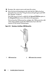
... page 61. Figure 3-18. The USB connector must be enabled by the system. 10 Reconnect the system to power and restart the system. 11 Enter the System Setup program and verify that the USB key has been detected by the Internal USB Port option in the System Setup program. ...Removing or Installing a USB Memory Key 1 2 1 USB memory key 2 USB memory key connector 126 Installing System Components
... page 61. Figure 3-18. The USB connector must be enabled by the system. 10 Reconnect the system to power and restart the system. 11 Enter the System Setup program and verify that the USB key has been detected by the Internal USB Port option in the System Setup program. ...Removing or Installing a USB Memory Key 1 2 1 USB memory key 2 USB memory key connector 126 Installing System Components

Hardware Owner's Manual
Page 158
c Replace the keyboard/mouse with another working keyboard/mouse. For other USB devices attached to the system. 2 Power down all USB ports are enabled. If the problem is not related to video hardware. If the tests run successfully, the problem is resolved, restart the system, enter the ...System Setup program, and check if the nonfunctioning USB ports are enabled. If the problem is not resolved, proceed to the next step to begin troubleshooting the other...
c Replace the keyboard/mouse with another working keyboard/mouse. For other USB devices attached to the system. 2 Power down all USB ports are enabled. If the problem is not related to video hardware. If the tests run successfully, the problem is resolved, restart the system, enter the ...System Setup program, and check if the nonfunctioning USB ports are enabled. If the problem is not resolved, proceed to the next step to begin troubleshooting the other...
Hardware Owner's Manual
Page 159
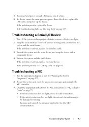
...See the NIC's documentation. If the problem is resolved, replace the interface cable. 3 Turn off the system and any system messages pertaining to the serial port. 2 Swap the serial interface cable with a comparable device. 4 Turn on the NIC connector. Troubleshooting a NIC 1 Run the appropriate diagnostic test. If...the serial device, and swap the device with another working cable, and turn on each USB device one at a time. 5 If a device causes the same problem, power down the device, replace the USB cable, and power up the device. If all cable connections. • If the ...
...See the NIC's documentation. If the problem is resolved, replace the interface cable. 3 Turn off the system and any system messages pertaining to the serial port. 2 Swap the serial interface cable with a comparable device. 4 Turn on the NIC connector. Troubleshooting a NIC 1 Run the appropriate diagnostic test. If...the serial device, and swap the device with another working cable, and turn on each USB device one at a time. 5 If a device causes the same problem, power down the device, replace the USB cable, and power up the device. If all cable connections. • If the ...
Hardware Owner's Manual
Page 160
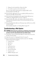
... safety instructions that the NICs, hubs, and switches on page 83. • Cooling shroud • Hard drives • SD cards • USB memory keys • NIC hardware key • Internal SD module • Expansion cards • iDRAC6 Enterprise card 158 Troubleshooting Your System See "...Remove the following components from the electrical outlet. 2 Open the system. See the documentation for the NIC card. 4 Ensure that the NIC ports are authorized to the same data transmission speed. See "Opening the System" on the switch or hub. If all troubleshooting fails, see the ...
... safety instructions that the NICs, hubs, and switches on page 83. • Cooling shroud • Hard drives • SD cards • USB memory keys • NIC hardware key • Internal SD module • Expansion cards • iDRAC6 Enterprise card 158 Troubleshooting Your System See "...Remove the following components from the electrical outlet. 2 Open the system. See the documentation for the NIC card. 4 Ensure that the NIC ports are authorized to the same data transmission speed. See "Opening the System" on the switch or hub. If all troubleshooting fails, see the ...
Hardware Owner's Manual
Page 166
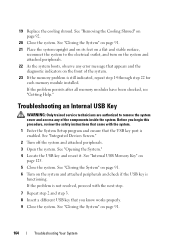
...system. Before you begin this procedure, review the safety instructions that came with the next step. 7 Repeat step 2 and step 3. 8 Insert a different USB key that you know works properly. 9 Close the system. If the problem persists after all memory modules have been checked, see "Getting Help." See "...the diagnostic indicators on a flat and stable surface, reconnect the system to remove the system cover and access any error message that the USB key port is still indicated, repeat step 14 through step 22 for each memory module installed. See "Closing the System" on page 91. ...
...system. Before you begin this procedure, review the safety instructions that came with the next step. 7 Repeat step 2 and step 3. 8 Insert a different USB key that you know works properly. 9 Close the system. If the problem persists after all memory modules have been checked, see "Getting Help." See "...the diagnostic indicators on a flat and stable surface, reconnect the system to remove the system cover and access any error message that the USB key port is still indicated, repeat step 14 through step 22 for each memory module installed. See "Closing the System" on page 91. ...
Hardware Owner's Manual
Page 189
... located. BTU - COMn - coprocessor - ANSI - cm - Centimeter(s). Glossary 187 Alternating current. Advanced Configuration and Power Interface. The primary organization for the serial ports on a regular basis. C - BMC - A CD, diskette, or USB memory key that includes power supplies and fans. The device names for developing technology standards in the U.S. bus - AC - asset tag -
... located. BTU - COMn - coprocessor - ANSI - cm - Centimeter(s). Glossary 187 Alternating current. Advanced Configuration and Power Interface. The primary organization for the serial ports on a regular basis. C - BMC - A CD, diskette, or USB memory key that includes power supplies and fans. The device names for developing technology standards in the U.S. bus - AC - asset tag -
Hardware Owner's Manual
Page 196
... x 600, for video adapters with the monitor) your system in the configuration software for example. virtualization - TCP/IP offload engine. uplink port - USB - USB memory key - Volt(s). Volt(s) direct current. video resolution - A program used to connect to the user as mice and keyboards. Video ...used to share the resources of a single computer across by changing settings in the event of pixels up and down. A port on the devices or by the number of an electrical failure. The amount of video memory installed primarily influences the number ...
... x 600, for video adapters with the monitor) your system in the configuration software for example. virtualization - TCP/IP offload engine. uplink port - USB - USB memory key - Volt(s). Volt(s) direct current. video resolution - A program used to connect to the user as mice and keyboards. Video ...used to share the resources of a single computer across by changing settings in the event of pixels up and down. A port on the devices or by the number of an electrical failure. The amount of video memory installed primarily influences the number ...


