

Glossary
Page 8
...As the main circuit board, the system board usually contains most of your system in an array, but only uses a portion of a SCSI cable) must be configured for operation. See RAM. An unregistered (unbuffered) DDR3 memory module. A port on each disk used by an operating system... can be connected and disconnected while the system is installed and how the system should be terminated to other hubs or switches without requiring a crossover cable. UPS - USB - System Setup program - TCP/IP - termination - Data stored in effect until you may use several stripes on each disk...
...As the main circuit board, the system board usually contains most of your system in an array, but only uses a portion of a SCSI cable) must be configured for operation. See RAM. An unregistered (unbuffered) DDR3 memory module. A port on each disk used by an operating system... can be connected and disconnected while the system is installed and how the system should be terminated to other hubs or switches without requiring a crossover cable. UPS - USB - System Setup program - TCP/IP - termination - Data stored in effect until you may use several stripes on each disk...
Getting Started Guide
Page 6
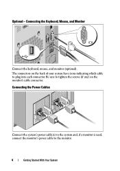
Optional - The connectors on the monitor's cable connector. Connecting the Power Cables Connect the system's power cable(s) to the system and, if a monitor is used, connect the monitor's power cable to plug into each connector. Be sure to tighten the screws (if any) on the back of your system have icons indicating which cable to the monitor. 4 Getting Started With Your System Connecting the Keyboard, Mouse, and Monitor Connect the keyboard, mouse, and monitor (optional).
Optional - The connectors on the monitor's cable connector. Connecting the Power Cables Connect the system's power cable(s) to the system and, if a monitor is used, connect the monitor's power cable to plug into each connector. Be sure to tighten the screws (if any) on the back of your system have icons indicating which cable to the monitor. 4 Getting Started With Your System Connecting the Keyboard, Mouse, and Monitor Connect the keyboard, mouse, and monitor (optional).
Getting Started Guide
Page 7
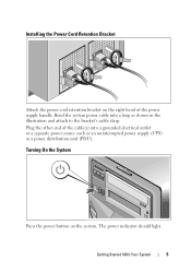
The power indicator should light. Plug the other end of the power supply handle. Turning On the System Press the power button on the right bend of the cable(s) into a loop as an uninterrupted power supply (UPS) or a power distribution unit (PDU). Getting Started With Your System 5 Bend the system power cable into a grounded electrical outlet or a separate power source such as shown in the illustration and attach to the bracket's cable clasp. Installing the Power Cord Retention Bracket Attach the power cord retention bracket on the system.
The power indicator should light. Plug the other end of the power supply handle. Turning On the System Press the power button on the right bend of the cable(s) into a loop as an uninterrupted power supply (UPS) or a power distribution unit (PDU). Getting Started With Your System 5 Bend the system power cable into a grounded electrical outlet or a separate power source such as shown in the illustration and attach to the bracket's cable clasp. Installing the Power Cord Retention Bracket Attach the power cord retention bracket on the system.
Getting Started Guide
Page 11
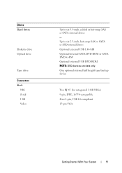
One optional internal half height tape backup device Two RJ-45 (for integrated 1-GB NICs) 9-pin, DTE, 16550-compatible Four 4-pin, USB 2.0-compliant 15-pin VGA Getting Started With Your System 9 Drives Hard drives Diskette drive Optical drive Tape drive Connectors Back NIC Serial USB Video Up to six 3.5-inch, cabled or hot-swap SAS or SATA internal drives or Up to six 2.5-inch, hot-swap SAS or SATA or SSD internal drives Optional external USB 1.44-MB Optional internal SATA DVD-ROM or SATA DVD+/-RW Optional external USB DVD-ROM NOTE: DVD devices are data only.
One optional internal half height tape backup device Two RJ-45 (for integrated 1-GB NICs) 9-pin, DTE, 16550-compatible Four 4-pin, USB 2.0-compliant 15-pin VGA Getting Started With Your System 9 Drives Hard drives Diskette drive Optical drive Tape drive Connectors Back NIC Serial USB Video Up to six 3.5-inch, cabled or hot-swap SAS or SATA internal drives or Up to six 2.5-inch, hot-swap SAS or SATA or SSD internal drives Optional external USB 1.44-MB Optional internal SATA DVD-ROM or SATA DVD+/-RW Optional external USB DVD-ROM NOTE: DVD devices are data only.
Hardware Owner's Manual
Page 6
... Bay 94 Installing a Drive Blank in the Front Bay 94 Removing a Hot-Swap Hard Drive 94 Installing a Hot-Swap Hard Drive 96 Removing a Cabled Hard Drive 98 Installing a Cabled Hard Drive 100 Optical and Tape Drives 102 Removing an Optical or a Tape Drive 102 Installing an Optical or Tape Drive 103 System...
... Bay 94 Installing a Drive Blank in the Front Bay 94 Removing a Hot-Swap Hard Drive 94 Installing a Hot-Swap Hard Drive 96 Removing a Cabled Hard Drive 98 Installing a Cabled Hard Drive 100 Optical and Tape Drives 102 Removing an Optical or a Tape Drive 102 Installing an Optical or Tape Drive 103 System...
Hardware Owner's Manual
Page 22
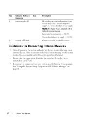
... supply or a non-redundant power supply. Turn on any external devices before attaching a new external device. Item Indicator, Button, or Icon Connector 8 power supplies (2) 9 security cable slot Description Depending on your configuration, your system, use the System Setup program. Redundant power supply - 580 W Non-redundant power supply - 525 W Connects...
... supply or a non-redundant power supply. Turn on any external devices before attaching a new external device. Item Indicator, Button, or Icon Connector 8 power supplies (2) 9 security cable slot Description Depending on your configuration, your system, use the System Setup program. Redundant power supply - 580 W Non-redundant power supply - 525 W Connects...

Hardware Owner's Manual
Page 32
... "Getting Help" on page 161. 32 About Your System E1614 Power Supply # (### W) error. caused the predictive warning of an impending power supply failure. Check PSU cables. Check the AC power source for 10 seconds and restart the system. LCD Status Messages (continued) Code Text Causes Corrective Actions E1420 CPU Bus parity...
... "Getting Help" on page 161. 32 About Your System E1614 Power Supply # (### W) error. caused the predictive warning of an impending power supply failure. Check PSU cables. Check the AC power source for 10 seconds and restart the system. LCD Status Messages (continued) Code Text Causes Corrective Actions E1420 CPU Bus parity...
Hardware Owner's Manual
Page 33
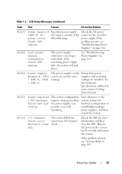
... power supply. Remove AC power to the system, reduce the hardware configuration or install higher-wattage power supplies, and then restart the system. Check PSU cables. E1624 Lost power supply redundancy. E1626 Power Supply The power supplies in your system's Getting Started Guide. the Technical Specifications outlined in the Ensure that... Power Supply # (### W) AC power error. Specified power supply's AC input is no longer redundant. reported an I /O channel The system BIOS has check error. Check PSU cables. E1710 I /O channel Review & clear check.
... power supply. Remove AC power to the system, reduce the hardware configuration or install higher-wattage power supplies, and then restart the system. Check PSU cables. E1624 Lost power supply redundancy. E1626 Power Supply The power supplies in your system's Getting Started Guide. the Technical Specifications outlined in the Ensure that... Power Supply # (### W) AC power error. Specified power supply's AC input is no longer redundant. reported an I /O channel The system BIOS has check error. Check PSU cables. E1710 I /O channel Review & clear check.

Hardware Owner's Manual
Page 35
..." on page 185. Check bad. If the problem persists, replace cable. About Your System 35 See the card is missing or Reseat the cable. Check bad. problem persists, replace connection. cable. Reseat the cable. E1A14 SAS cable A SAS cable A is bad. Table 1-2. Check has been removed from drive..... E1920 iDRAC6 Upgrade The iDRAC6 Express card Reseat the iDRAC6 Failed is missing or Reseat the cable. If the problem persists, see "Getting Help" on page 185. Check cable. If the problem persists, see "Getting Help" on page 185. E1812 Hard drive ## The...
..." on page 185. Check bad. If the problem persists, replace cable. About Your System 35 See the card is missing or Reseat the cable. Check bad. problem persists, replace connection. cable. Reseat the cable. E1A14 SAS cable A SAS cable A is bad. Table 1-2. Check has been removed from drive..... E1920 iDRAC6 Upgrade The iDRAC6 Express card Reseat the iDRAC6 Failed is missing or Reseat the cable. If the problem persists, see "Getting Help" on page 185. Check cable. If the problem persists, see "Getting Help" on page 185. E1812 Hard drive ## The...
Hardware Owner's Manual
Page 42
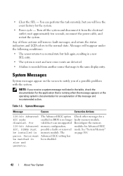
... detected. • A failure is recorded from the electrical outlet; NOTE: If you of the message and recommended action. wait approximately ten seconds, reconnect the power cable, and restart the system. • Clear the SEL - You can perform this task remotely, but fails again, resulting in the table, check the documentation for...
... detected. • A failure is recorded from the electrical outlet; NOTE: If you of the message and recommended action. wait approximately ten seconds, reconnect the power cable, and restart the system. • Clear the SEL - You can perform this task remotely, but fails again, resulting in the table, check the documentation for...
Hardware Owner's Manual
Page 47
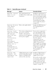
...system NICy: in the slot! About Your System 47 Embedded NICx and The OS NIC interface is installed in BIOS. Mouse or keyboard cable is operational. See "Troubleshooting a USB Device" on page 106. See "Getting Help" on page 61. Ensure that mouse and ...keyboard are installed in the dedicated slot. Reseat the mouse or keyboard cable. The memory module configuration for each CPU should match. The Management management software or the OS NIC=, management tools. Run the System...
...system NICy: in the slot! About Your System 47 Embedded NICx and The OS NIC interface is installed in BIOS. Mouse or keyboard cable is operational. See "Troubleshooting a USB Device" on page 106. See "Getting Help" on page 61. Ensure that mouse and ...keyboard are installed in the dedicated slot. Reseat the mouse or keyboard cable. The memory module configuration for each CPU should match. The Management management software or the OS NIC=, management tools. Run the System...
Hardware Owner's Manual
Page 51
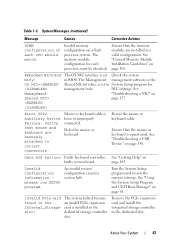
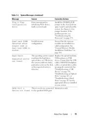
... port. "Troubleshooting a USB Device" on page 156, "Troubleshooting an Optical Drive" on page 165, or "Troubleshooting a Hard Drive" on the disk, cables, or optical drive cables or the requested sector is no device connected Information only. If the problem persists, see "Troubleshooting the Processors" on page 106. Quad rank DIMM...Your System 51 faulty system board. See "General Memory Module Installation Guidelines" on page 171. Ensure that the USB the system could not find a cables, SAS/SATA backplane particular sector on page 167 for jumper location. Table 1-3.
... port. "Troubleshooting a USB Device" on page 156, "Troubleshooting an Optical Drive" on page 165, or "Troubleshooting a Hard Drive" on the disk, cables, or optical drive cables or the requested sector is no device connected Information only. If the problem persists, see "Troubleshooting the Processors" on page 106. Quad rank DIMM...Your System 51 faulty system board. See "General Memory Module Installation Guidelines" on page 171. Ensure that the USB the system could not find a cables, SAS/SATA backplane particular sector on page 167 for jumper location. Table 1-3.
Hardware Owner's Manual
Page 52
... has Sparing mode. If memory has been added or removed, this message is informative and can be faulty. Ensure that the USB or SAS backplane cables are properly connected. See "Troubleshooting a USB Device" on page 156 or "Troubleshooting a Hard Drive" on page 185. Sparing mode disabled. See "System been disabled. See...
... has Sparing mode. If memory has been added or removed, this message is informative and can be faulty. Ensure that the USB or SAS backplane cables are properly connected. See "Troubleshooting a USB Device" on page 156 or "Troubleshooting a Hard Drive" on page 185. Sparing mode disabled. See "System been disabled. See...
Hardware Owner's Manual
Page 57
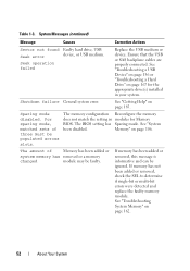
System Messages (continued) Message Causes Corrective Actions Warning: Control Panel is not Install the control panel, or installed or has a faulty cable check the cable connections connection. See "Getting Help" on one power supply until you can also run the system on page 185. Warning! System will reboot. You can ...
System Messages (continued) Message Causes Corrective Actions Warning: Control Panel is not Install the control panel, or installed or has a faulty cable check the cable connections connection. See "Getting Help" on one power supply until you can also run the system on page 185. Warning! System will reboot. You can ...
Hardware Owner's Manual
Page 58
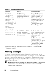
... continues a task. NOTE: Warning messages are properly connected. If the problem persists, see the "Glossary" on the diskette. Write fault Write fault on page 106. cables are generated by typing y (yes) or n (no). Warning Messages A warning message alerts you to a possible problem and prompts you to respond before you may lose...
... continues a task. NOTE: Warning messages are properly connected. If the problem persists, see the "Glossary" on the diskette. Write fault Write fault on page 106. cables are generated by typing y (yes) or n (no). Warning Messages A warning message alerts you to a possible problem and prompts you to respond before you may lose...
Hardware Owner's Manual
Page 83
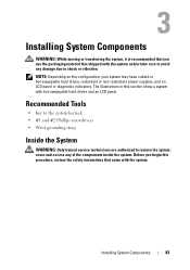
NOTE: Depending on the configuration, your system may have cabled or hot-swappable hard drives, redundant or non-redundant power supplies, and an LCD panel or diagnostic indicators. Recommended Tools • Key to the system ...
NOTE: Depending on the configuration, your system may have cabled or hot-swappable hard drives, redundant or non-redundant power supplies, and an LCD panel or diagnostic indicators. Recommended Tools • Key to the system ...
Hardware Owner's Manual
Page 91
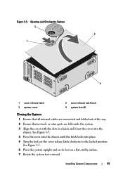
... locked position. Opening and Closing the System 2 3 1 4 1 cover release latch 3 system cover 2 cover release latch lock 4 system feet (4) Closing the System 1 Ensure that all internal cables are connected and folded out of the way. 2 Ensure that no tools or extra parts are left inside the system. 3 Align the cover with the...
... locked position. Opening and Closing the System 2 3 1 4 1 cover release latch 3 system cover 2 cover release latch lock 4 system feet (4) Closing the System 1 Ensure that all internal cables are connected and folded out of the way. 2 Ensure that no tools or extra parts are left inside the system. 3 Align the cover with the...
Hardware Owner's Manual
Page 93
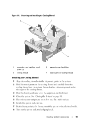
... Shroud 1 Align the cooling shroud with the alignment guides in the system. 2 Hold the touch points on the system and attached peripherals. Ensure that no cables are pinned under the edges of the cooling shroud. 3 Hold the touch points and lower the expansion card stabilizer. 4 Close the system. Figure 3-6. Installing System...
... Shroud 1 Align the cooling shroud with the alignment guides in the system. 2 Hold the touch points on the system and attached peripherals. Ensure that no cables are pinned under the edges of the cooling shroud. 3 Hold the touch points and lower the expansion card stabilizer. 4 Close the system. Figure 3-6. Installing System...
Hardware Owner's Manual
Page 98
... 3-7. 6 Replace the front bezel. See Figure 3-9. 98 Installing System Components See "Opening the System" on page 90. 4 Disconnect the power and data cable from the peripherals. 2 Rotate the system feet inward and lay the system on page 86. 4 With the lever on the hard drive carrier open, slide...drive bracket towards the system) on the hard drive carrier and rotate the handle up until the carrier contacts the backplane. Removing a Cabled Hard Drive WARNING: Only trained service technicians are authorized to remove the system cover and access any components inside the system.
... 3-7. 6 Replace the front bezel. See Figure 3-9. 98 Installing System Components See "Opening the System" on page 90. 4 Disconnect the power and data cable from the peripherals. 2 Rotate the system feet inward and lay the system on page 86. 4 With the lever on the hard drive carrier open, slide...drive bracket towards the system) on the hard drive carrier and rotate the handle up until the carrier contacts the backplane. Removing a Cabled Hard Drive WARNING: Only trained service technicians are authorized to remove the system cover and access any components inside the system.
Hardware Owner's Manual
Page 99
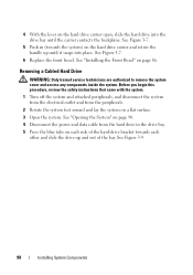
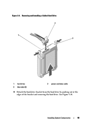
Installing System Components 99 Figure 3-9. See Figure 3-10. Removing and Installing a Cabled Hard Drive 2 1 3 1 hard drive 3 blue tabs (2) 2 power and data cable 6 Detach the hard-drive bracket from the hard drive by pushing out at the edges of the bracket and removing the hard drive.
Installing System Components 99 Figure 3-9. See Figure 3-10. Removing and Installing a Cabled Hard Drive 2 1 3 1 hard drive 3 blue tabs (2) 2 power and data cable 6 Detach the hard-drive bracket from the hard drive by pushing out at the edges of the bracket and removing the hard drive.


