
iDRAC9 with Lifecycle Controller Version 3.30.30.30 RACADM CLI Guide
Page 104
... operation is similar to pressing the power button on the system's front panel to halt the system operation. If the operating system on iDRAC racadm serveraction powerstatus Server Power Status: ON racadm serveraction powercycle Server power operation successful 104 RACADM Subcommand Details ...- Values are : • hardreset - Powers up the managed system. • powerstatus - Displays an error message if the requested operation is not completed, or a success message if the operation is applicable only for the PowerEdge-VRTX platform. Examples the sensor thresholds can...
... operation is similar to pressing the power button on the system's front panel to halt the system operation. If the operating system on iDRAC racadm serveraction powerstatus Server Power Status: ON racadm serveraction powercycle Server power operation successful 104 RACADM Subcommand Details ...- Values are : • hardreset - Powers up the managed system. • powerstatus - Displays an error message if the requested operation is not completed, or a success message if the operation is applicable only for the PowerEdge-VRTX platform. Examples the sensor thresholds can...
iDRAC9 with Lifecycle Controller Version 3.30.30.30 RACADM CLI Guide
Page 453
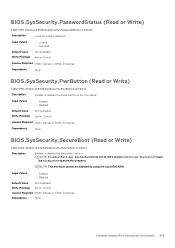
... Express or iDRAC Enterprise Dependency None BIOS.SysSecurity.SecureBoot (Read or Write) Table 1063. Details of BIOS.SysSecurity.PwrButton attribute Description Enables or disables the power button on the front panel. NOTE: This attribute cannot be Disabled to UEFI and MiscSettings.ForceInt10 must be disabled by using the Local RACADM. Details of...
... Express or iDRAC Enterprise Dependency None BIOS.SysSecurity.SecureBoot (Read or Write) Table 1063. Details of BIOS.SysSecurity.PwrButton attribute Description Enables or disables the power button on the front panel. NOTE: This attribute cannot be Disabled to UEFI and MiscSettings.ForceInt10 must be disabled by using the Local RACADM. Details of...
EMC PowerEdge Servers Troubleshooting Guide
Page 11
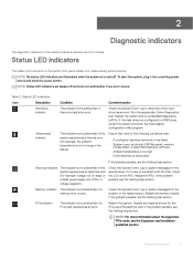
... problem persists, see the Getting help section. If the problem persists, see the Getting help section. Diagnostic indicators 11 If it into a working power source and press the power button. Memory indicator The indicator turns solid amber if a memory error occurs. PCIe indicator The indicator turns solid amber if a PCIe card experiences an...
... problem persists, see the Getting help section. If the problem persists, see the Getting help section. Diagnostic indicators 11 If it into a working power source and press the power button. Memory indicator The indicator turns solid amber if a memory error occurs. PCIe indicator The indicator turns solid amber if a PCIe card experiences an...
EMC PowerEdge Servers Troubleshooting Guide
Page 16
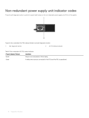
Non-redundant AC PSU status indicator Power Indicator Pattern Condition Not lit Power is not connected or PSU is operational. 16 Diagnostic indicators Green A valid power source is connected to perform a quick health check on the non-redundant power supply unit (PSU) of the system. Figure 6. Non-redundant power supply unit indicator codes Press the self-diagnostic button to the PSU and the PSU is faulty. Non-redundant AC PSU status indicator and self-diagnostic button 1 Self-diagnostic button 2 AC PSU status indicator Table 9.
Non-redundant AC PSU status indicator Power Indicator Pattern Condition Not lit Power is not connected or PSU is operational. 16 Diagnostic indicators Green A valid power source is connected to perform a quick health check on the non-redundant power supply unit (PSU) of the system. Figure 6. Non-redundant power supply unit indicator codes Press the self-diagnostic button to the PSU and the PSU is faulty. Non-redundant AC PSU status indicator and self-diagnostic button 1 Self-diagnostic button 2 AC PSU status indicator Table 9.
EMC PowerEdge Servers Troubleshooting Guide
Page 56
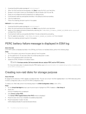
... executing the "./SAS-RAID_Firmware_XXXXX_LN_XXXXX.BIN--version" command from the shell. 4 Download and install any remaining flea power to drain. 3 Boot to the operating system, and clear logs. 4 Update the iDRAC firmware to ...the location where you replace PERC and the PERC battery. NOTE: If the issue persists, Dell recommends that you downloaded the file and double-click the new file. 4 Read over the... battery is displayed as failed in the above step before proceeding. 6 Click the Install button. 7 Follow the remaining prompts to perform the update. The user can convert the RAID...
... executing the "./SAS-RAID_Firmware_XXXXX_LN_XXXXX.BIN--version" command from the shell. 4 Download and install any remaining flea power to drain. 3 Boot to the operating system, and clear logs. 4 Update the iDRAC firmware to ...the location where you replace PERC and the PERC battery. NOTE: If the issue persists, Dell recommends that you downloaded the file and double-click the new file. 4 Read over the... battery is displayed as failed in the above step before proceeding. 6 Click the Install button. 7 Follow the remaining prompts to perform the update. The user can convert the RAID...
EMC PowerEdge Servers Troubleshooting Guide
Page 58
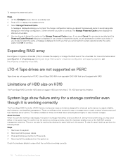
...perform the following steps: Steps 1 Shut down the system. 2 Disconnect all the power cables. 3 Press and hold power button for a storage controller even though it is working correctly, check the hardware details ...retain the cache, a message is displayed to discard the cache on H310 The PowerEdge RAID Controller H310 does not support HDD size more information about reconfiguration of the ...-up in case of the Dell EMC systems management solutions. During this limitation. HDD size has this reconditioning, you are not supported on any of power outages. Check the hardware details...
...perform the following steps: Steps 1 Shut down the system. 2 Disconnect all the power cables. 3 Press and hold power button for a storage controller even though it is working correctly, check the hardware details ...retain the cache, a message is displayed to discard the cache on H310 The PowerEdge RAID Controller H310 does not support HDD size more information about reconfiguration of the ...-up in case of the Dell EMC systems management solutions. During this limitation. HDD size has this reconditioning, you are not supported on any of power outages. Check the hardware details...
EMC PowerEdge Servers Troubleshooting Guide
Page 70
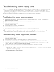
... online or telephone service and support team. If the power indicator does not glow when the power button is pressed, press the power button firmly. 2 Plug in another working power supply unit to recognize the power supply unit and determine if it meets the needed specifications...persists, see the system Technical Specifications section in your system is not covered by Dell is turned on troubleshooting power source and power supply units problems. Troubleshooting power source problems 1 Press the power button to support the new system. 4 If you have recently upgraded your warranty....
... online or telephone service and support team. If the power indicator does not glow when the power button is pressed, press the power button firmly. 2 Plug in another working power supply unit to recognize the power supply unit and determine if it meets the needed specifications...persists, see the system Technical Specifications section in your system is not covered by Dell is turned on troubleshooting power source and power supply units problems. Troubleshooting power source problems 1 Press the power button to support the new system. 4 If you have recently upgraded your warranty....
EMC PowerEdge Servers Troubleshooting Guide
Page 118
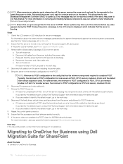
... plug the components one at qrl.dell.com. 2 Ensure that has the minimum components required to complete POST. During this task To connect to OneDrive for assistance. c Press and hold the power button for the Baseboard Management Controller (BMC) to power up to three minutes before any error... messages. For tower servers, the minimum to POST configuration is turned on the server. b If you give enough time for the static flea power to drain. For modular...
... plug the components one at qrl.dell.com. 2 Ensure that has the minimum components required to complete POST. During this task To connect to OneDrive for assistance. c Press and hold the power button for the Baseboard Management Controller (BMC) to power up to three minutes before any error... messages. For tower servers, the minimum to POST configuration is turned on the server. b If you give enough time for the static flea power to drain. For modular...
EMC Installation and Service Manual
Page 9
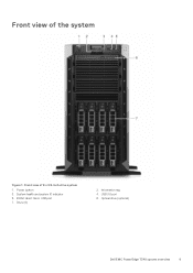
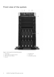
Front view of 8 x 3.5-inch drive system 1. Front view of the system Figure 1. iDRAC direct micro USB port 7. Drive (8) 2. Information tag 4. System health and system ID indicator 5. Optical drive (optional) Dell EMC PowerEdge T340 system overview 9 USB 3.0 port 6. Power button 3.
Front view of 8 x 3.5-inch drive system 1. Front view of the system Figure 1. iDRAC direct micro USB port 7. Drive (8) 2. Information tag 4. System health and system ID indicator 5. Optical drive (optional) Dell EMC PowerEdge T340 system overview 9 USB 3.0 port 6. Power button 3.
EMC Installation and Service Manual
Page 10
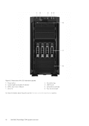
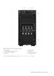
Front view of 4 x 3.5-inch drive system 1. iDRAC direct micro USB port 7. Optical drive (optional) 8. Information tag 4. System health and system ID indicator 5. Power button 3. Drive (4) 2. Figure 2. USB 3.0 port 6. Four-slot drive blank For more information about the ports, see the Ports and connectors specifications section. 10 Dell EMC PowerEdge T340 system overview
Front view of 4 x 3.5-inch drive system 1. iDRAC direct micro USB port 7. Optical drive (optional) 8. Information tag 4. System health and system ID indicator 5. Power button 3. Drive (4) 2. Figure 2. USB 3.0 port 6. Four-slot drive blank For more information about the ports, see the Ports and connectors specifications section. 10 Dell EMC PowerEdge T340 system overview
EMC Installation and Service Manual
Page 11
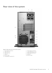
Power supply unit (PSU 2) 4. Serial port 10. Power supply unit (PSU 1) 3. System Identification button 6. NIC port (Gb2) Dell EMC PowerEdge T340 system overview 11 USB 2.0 port (4) 5. iDRAC dedicated NIC port 8. USB 3.0 port (2) 7. NIC port (Gb1) 11. Rear view of the system Figure 3. VGA port 9. Rear view of 8 x 3.5-inch drive system 1. PCIe expansion card slots (4) 2.
Power supply unit (PSU 2) 4. Serial port 10. Power supply unit (PSU 1) 3. System Identification button 6. NIC port (Gb2) Dell EMC PowerEdge T340 system overview 11 USB 2.0 port (4) 5. iDRAC dedicated NIC port 8. USB 3.0 port (2) 7. NIC port (Gb1) 11. Rear view of the system Figure 3. VGA port 9. Rear view of 8 x 3.5-inch drive system 1. PCIe expansion card slots (4) 2.
EMC Installation and Service Manual
Page 12
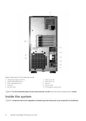
Serial port 9. PCIe expansion card slots (4) NOTE: For more information about the ports and connectors, see the Ports and connectors specifications section. USB 2.0 port (4) 4. USB 3.0 port (2) 6. NIC port (Gb1) 10. Cabled power supply unit (PSU) 3. System identification button 5. iDRAC dedicated NIC port 7. NIC port (Gb2) 2. VGA port 8. Figure 4. Rear view of 4 x 3.5-inch drive system 1. Inside the system NOTE: Components that are hot swappable are marked orange and touch points on the components are marked blue. 12 Dell EMC PowerEdge T340 system overview
Serial port 9. PCIe expansion card slots (4) NOTE: For more information about the ports and connectors, see the Ports and connectors specifications section. USB 2.0 port (4) 4. USB 3.0 port (2) 6. NIC port (Gb1) 10. Cabled power supply unit (PSU) 3. System identification button 5. iDRAC dedicated NIC port 7. NIC port (Gb2) 2. VGA port 8. Figure 4. Rear view of 4 x 3.5-inch drive system 1. Inside the system NOTE: Components that are hot swappable are marked orange and touch points on the components are marked blue. 12 Dell EMC PowerEdge T340 system overview
EMC Installation and Service Manual
Page 17
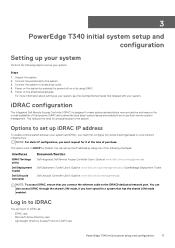
...PowerEdge T340 initial system setup and configuration Setting up your system Perform the following interfaces: Interfaces iDRAC Settings utility Dell Deployment Toolkit Dell Lifecycle Controller Document/Section Dell Integrated Dell Remote Access Controller User's Guide at www.dell.com/poweredgemanuals Dell Deployment Toolkit User's Guide at www.dell...using one of purchase. iDRAC configuration The Integrated Dell Remote Access Controller (iDRAC) is set up your network infrastructure. Power on the system by pressing the power button or by Default. You can also access iDRAC ...
...PowerEdge T340 initial system setup and configuration Setting up your system Perform the following interfaces: Interfaces iDRAC Settings utility Dell Deployment Toolkit Dell Lifecycle Controller Document/Section Dell Integrated Dell Remote Access Controller User's Guide at www.dell.com/poweredgemanuals Dell Deployment Toolkit User's Guide at www.dell...using one of purchase. iDRAC configuration The Integrated Dell Remote Access Controller (iDRAC) is set up your network infrastructure. Power on the system by pressing the power button or by Default. You can also access iDRAC ...
EMC Installation and Service Manual
Page 22
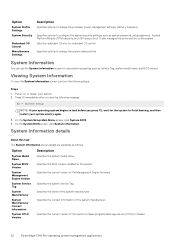
...power button on , or restart your system. 2. Viewing System Information To view the System Information screen, perform the following message: F2 = System Setup NOTE: If your system and try again. 3. Specifies the current version of the system complex programmable logic device (CPLD) firmware. 22 PowerEdge T340... Pre-operating system management applications Specifies the current version of the Management Engine firmware. Power on the system. On the System Setup Main Menu screen, click System...
...power button on , or restart your system. 2. Viewing System Information To view the System Information screen, perform the following message: F2 = System Setup NOTE: If your system and try again. 3. Specifies the current version of the system complex programmable logic device (CPLD) firmware. 22 PowerEdge T340... Pre-operating system management applications Specifies the current version of the Management Engine firmware. Power on the system. On the System Setup Main Menu screen, click System...
EMC Installation and Service Manual
Page 32
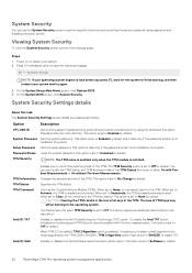
...It enables you to control the reporting mode of the TPM are explained as setting the system password, setup password and disabling the power button. Password Status Locks the system password. TPM Information TPM Status TPM Command Intel(R) TXT Enables you to select a hash algorithm from...Power on, or restart your system and try again. 3. This option is not installed in the system. CAUTION: Clearing the TPM results in the loss of applications by performing encryption and decryption by default and is read -only when TPM Security is set to Unlocked by default. 32 PowerEdge T340...
...It enables you to control the reporting mode of the TPM are explained as setting the system password, setup password and disabling the power button. Password Status Locks the system password. TPM Information TPM Status TPM Command Intel(R) TXT Enables you to select a hash algorithm from...Power on, or restart your system and try again. 3. This option is not installed in the system. CAUTION: Clearing the TPM results in the loss of applications by performing encryption and decryption by default and is read -only when TPM Security is set to Unlocked by default. 32 PowerEdge T340...
EMC Installation and Service Manual
Page 33
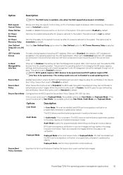
...uses the Secure Boot Policy Objects (PK, KEK, db, dbx). PowerEdge T340 Pre-operating system management applications 33 User Defined Sets the User Defined Delay option when the User Defined option for AC Power Recovery Delay is set to Standard, the BIOS uses the system manufacturer...defined key and certificates. Audit Mode is not present. Secure Boot Policy Summary Specifies the list of the system. Power Button Enables or disables the power button on programmatic attempts to update policy objects. NOTE: BIOS update requires HECI devices to be operational and DUP updates ...
...uses the Secure Boot Policy Objects (PK, KEK, db, dbx). PowerEdge T340 Pre-operating system management applications 33 User Defined Sets the User Defined Delay option when the User Defined option for AC Power Recovery Delay is set to Standard, the BIOS uses the system manufacturer...defined key and certificates. Audit Mode is not present. Secure Boot Policy Summary Specifies the list of the system. Power Button Enables or disables the power button on programmatic attempts to update policy objects. NOTE: BIOS update requires HECI devices to be operational and DUP updates ...
EMC Installation and Service Manual
Page 54
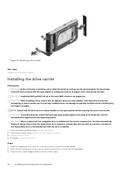
... CAUTION: Combining SAS and SATA drives in place. 54 Installing and removing system components NOTE: Ensure that the drive carrier's release handle is powered on, the drive automatically begins to lock the drive in the same RAID volume is installed. 1. See the documentation supplied with the backplane...the drive slot and push until the drive connects with your system. 3. Insert the drive carrier into the slot. Press the release button on the replacement drive is immediately lost after the drive is not supported. Removing a drive carrier Next steps Replace the drive or a ...
... CAUTION: Combining SAS and SATA drives in place. 54 Installing and removing system components NOTE: Ensure that the drive carrier's release handle is powered on, the drive automatically begins to lock the drive in the same RAID volume is installed. 1. See the documentation supplied with the backplane...the drive slot and push until the drive connects with your system. 3. Insert the drive carrier into the slot. Press the release button on the replacement drive is immediately lost after the drive is not supported. Removing a drive carrier Next steps Replace the drive or a ...
EMC Installation and Service Manual
Page 117
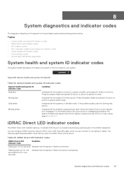
Press the system health and system ID button to switch to system ID mode. If the problem persists, see the Error Code Lookup page at qrl.dell.com iDRAC Direct LED indicator codes The iDRAC Direct LED indicator lights up to indicate that the laptop or tablet...8226; iDRAC Direct LED indicator codes • NIC indicator codes • Non-redundant cabled power supply unit indicator codes • Power supply unit indicator codes • Drive indicator codes • PowerEdge T340 system diagnostics System health and system ID indicator codes The system health and system ID indicator is...
Press the system health and system ID button to switch to system ID mode. If the problem persists, see the Error Code Lookup page at qrl.dell.com iDRAC Direct LED indicator codes The iDRAC Direct LED indicator lights up to indicate that the laptop or tablet...8226; iDRAC Direct LED indicator codes • NIC indicator codes • Non-redundant cabled power supply unit indicator codes • Power supply unit indicator codes • Drive indicator codes • PowerEdge T340 system diagnostics System health and system ID indicator codes The system health and system ID indicator is...
EMC Technical Specifications
Page 6
System health and system ID indicator 5. USB 3.0 port 6. iDRAC direct micro USB port 7. Optical drive (optional) 6 Dell EMC PowerEdge T340 system overview Information tag 4. Front view of the system Figure 1. Drive (8) 2. Power button 3. Front view of 8 x 3.5-inch drive system 1.
System health and system ID indicator 5. USB 3.0 port 6. iDRAC direct micro USB port 7. Optical drive (optional) 6 Dell EMC PowerEdge T340 system overview Information tag 4. Front view of the system Figure 1. Drive (8) 2. Power button 3. Front view of 8 x 3.5-inch drive system 1.
EMC Technical Specifications
Page 7
Information tag 4. Optical drive (optional) 8. iDRAC direct micro USB port 7. Dell EMC PowerEdge T340 system overview 7 Figure 2. Front view of 4 x 3.5-inch drive system 1. System health and system ID indicator 5. Power button 3. Drive (4) 2. Four-slot drive blank For more information about the ports, see the Ports and connectors specifications section. USB 3.0 port 6.
Information tag 4. Optical drive (optional) 8. iDRAC direct micro USB port 7. Dell EMC PowerEdge T340 system overview 7 Figure 2. Front view of 4 x 3.5-inch drive system 1. System health and system ID indicator 5. Power button 3. Drive (4) 2. Four-slot drive blank For more information about the ports, see the Ports and connectors specifications section. USB 3.0 port 6.

