
Glossary
Page 2
.... A technology in memory modules that plugs into an expansion-card connector on both the rising and falling pulses of tests for peripherals, such as the power button and power indicator. device driver - A comprehensive set of a clock cycle. ERA - An add-in -line memory module. Dynamic Host Configuration Protocol. The device names for example...
.... A technology in memory modules that plugs into an expansion-card connector on both the rising and falling pulses of tests for peripherals, such as the power button and power indicator. device driver - A comprehensive set of a clock cycle. ERA - An add-in -line memory module. Dynamic Host Configuration Protocol. The device names for example...

User Manual
Page 5
Turning on the System If installed, remove the optional bezel. Turning On The System Figure 5. Press the power button. The power indicator should light. 5 Securing the Power Cable(s) Bend the system power cable into a grounded electrical outlet or a separate power source such as shown in the illustration and secure the cable to the bracket using the provided strap. Plug the other end of the power cable(s) into a loop as an uninterruptible power supply (UPS) or a power distribution unit (PDU). Securing The Power Cable(s) Figure 4.
Turning on the System If installed, remove the optional bezel. Turning On The System Figure 5. Press the power button. The power indicator should light. 5 Securing the Power Cable(s) Bend the system power cable into a grounded electrical outlet or a separate power source such as shown in the illustration and secure the cable to the bracket using the provided strap. Plug the other end of the power cable(s) into a loop as an uninterruptible power supply (UPS) or a power distribution unit (PDU). Securing The Power Cable(s) Figure 4.
Owner's Manual
Page 11
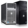
...Dell Remote Access Controller (iDRAC) (if not disabled in the 3.5 inch hard-drive carriers 11 Use this button only if directed to toggle the system ID on . Press to do so by qualified support personnel or by descriptive text. Item Indicator, Button, or Icon Description Connector 4 Power-on indicator, power button The power...-on indicator lights when the system power is on and off. The LCD lights amber when the system...
...Dell Remote Access Controller (iDRAC) (if not disabled in the 3.5 inch hard-drive carriers 11 Use this button only if directed to toggle the system ID on . Press to do so by qualified support personnel or by descriptive text. Item Indicator, Button, or Icon Description Connector 4 Power-on indicator, power button The power...-on indicator lights when the system power is on and off. The LCD lights amber when the system...
Owner's Manual
Page 13
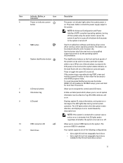
...out label panel which allows you to connect USB devices to display error status. The ports are USB 2.0-compliant. 13 The power button controls the power supply output to record system information such as Service Tag, NIC, MAC address, and so on. The diagnostic indicators light... up to the system. Item Indicator, Button, or Icon Description Connector 3 Power-on indicator, power button The power-on indicator lights when the system power is pressed again. If the system stops responding during POST, press and hold for ...
...out label panel which allows you to connect USB devices to display error status. The ports are USB 2.0-compliant. 13 The power button controls the power supply output to record system information such as Service Tag, NIC, MAC address, and so on. The diagnostic indicators light... up to the system. Item Indicator, Button, or Icon Description Connector 3 Power-on indicator, power button The power-on indicator lights when the system power is pressed again. If the system stops responding during POST, press and hold for ...

Owner's Manual
Page 14
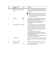
... within a rack. If the system stops responding during POST, press and hold the system ID button for more than five seconds to the system. The power button controls the power supply output to enter BIOS progress mode. 14 Press to toggle the system ID on the front...qualified support personnel or by the operating system documentation. Item Indicator, Button, or Icon Description Connector 1 Power-on indicator, power button The power-on . Front-Panel Features And Indicators-Rack Mode Figure 4. When one of these buttons is pressed, the LCD panel on the front and the system status...
... within a rack. If the system stops responding during POST, press and hold the system ID button for more than five seconds to the system. The power button controls the power supply output to enter BIOS progress mode. 14 Press to toggle the system ID on the front...qualified support personnel or by the operating system documentation. Item Indicator, Button, or Icon Description Connector 1 Power-on indicator, power button The power-on . Front-Panel Features And Indicators-Rack Mode Figure 4. When one of these buttons is pressed, the LCD panel on the front and the system status...
Owner's Manual
Page 15
The LCD lights blue during normal operating conditions and lights amber to the system. NOTE: If the system is connected to a power source and an error is installed with a double-width GPU card, the system supports only one 5.25 inch removable media storage device. 12 ..., the system supports only one of whether the system is operating correctly or when the system needs attention. Allow you to the system. Item Indicator, Button, or Icon Description Connector To reset iDRAC (if not disabled in 3.5 inch hard-drive carriers. • Up to sixteen 2.5 inch hot-swappable hard ...
The LCD lights blue during normal operating conditions and lights amber to the system. NOTE: If the system is connected to a power source and an error is installed with a double-width GPU card, the system supports only one 5.25 inch removable media storage device. 12 ..., the system supports only one of whether the system is operating correctly or when the system needs attention. Allow you to the system. Item Indicator, Button, or Icon Description Connector To reset iDRAC (if not disabled in 3.5 inch hard-drive carriers. • Up to sixteen 2.5 inch hot-swappable hard ...
Owner's Manual
Page 17
...on the Home screen. Diagnostic Indicators NOTE: Systems with an SEL entry. To start the system, plug it into a working power source and press the power button. The indicator blinks amber if the system is useful when trying to match an LCD message with cabled hard drives support diagnostic ... Model, or User String for the system Number Displays the Asset tag or the Service tag for iDRAC, iSCSI, or Network devices. Power Displays the power output of the system in the Set home submenu of the Setup menu. See System Error Messages for example, a failed fan specific issue...
...on the Home screen. Diagnostic Indicators NOTE: Systems with an SEL entry. To start the system, plug it into a working power source and press the power button. The indicator blinks amber if the system is useful when trying to match an LCD message with cabled hard drives support diagnostic ... Model, or User String for the system Number Displays the Asset tag or the Service tag for iDRAC, iSCSI, or Network devices. Power Displays the power output of the system in the Set home submenu of the Setup menu. See System Error Messages for example, a failed fan specific issue...

Owner's Manual
Page 20
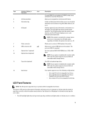
Non-redundant One 350 W non-redundant AC power power supply supply. 20 Back-Panel Features and Indicators Item Indicator, Button, or Icon Connector 1 Power supplies (PSU1 and PSU2) Description Redundant power supply Up to two 495 W or 750 W AC redundant power supplies. Back-Panel Features And Indicators Figure 7.
Non-redundant One 350 W non-redundant AC power power supply supply. 20 Back-Panel Features and Indicators Item Indicator, Button, or Icon Connector 1 Power supplies (PSU1 and PSU2) Description Redundant power supply Up to two 495 W or 750 W AC redundant power supplies. Back-Panel Features And Indicators Figure 7.

Owner's Manual
Page 21
... available for use only if the iDRAC7 Enterprise license is supported in F2 iDRAC setup), press and hold the system ID button for routing the power cable of these buttons is pressed again. If the system stops responding during POST, press and hold for more than 15 seconds. Allows you ...to connect a serial device to the system. Item Indicator, Button, or Icon Description Connector NOTE: Non-redundant power supply is installed on and off. Two integrated 10/100/1000 Mbps NIC connectors. Allows you to connect USB devices to...
... available for use only if the iDRAC7 Enterprise license is supported in F2 iDRAC setup), press and hold the system ID button for routing the power cable of these buttons is pressed again. If the system stops responding during POST, press and hold for more than 15 seconds. Allows you ...to connect a serial device to the system. Item Indicator, Button, or Icon Description Connector NOTE: Non-redundant power supply is installed on and off. Two integrated 10/100/1000 Mbps NIC connectors. Allows you to connect USB devices to...

Owner's Manual
Page 23
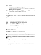
... receive different input voltages, they must power down the system. Green A valid power source is connected to the power supply and the power supply is operational. Power Indicator Codes For Non-Redundant Power Supply Press the self-diagnostic button to perform a quick health check on the non-redundant power supply of the other power supply (in an error condition...
... receive different input voltages, they must power down the system. Green A valid power source is connected to the power supply and the power supply is operational. Power Indicator Codes For Non-Redundant Power Supply Press the self-diagnostic button to perform a quick health check on the non-redundant power supply of the other power supply (in an error condition...
Owner's Manual
Page 24
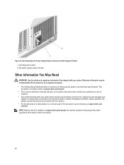
... the safety and regulatory information that you purchased with your system. Figure 10. Non-Redundant AC Power Supply Status Indicator and Self-Diagnostic Button 1. Warranty information may be included within this document, see the Glossary at support.dell.com/manuals. • The rack documentation included with your rack solution describes how to the...
... the safety and regulatory information that you purchased with your system. Figure 10. Non-Redundant AC Power Supply Status Indicator and Self-Diagnostic Button 1. Warranty information may be included within this document, see the Glossary at support.dell.com/manuals. • The rack documentation included with your rack solution describes how to the...

Owner's Manual
Page 27
... mode (BIOS or UEFI). Boot Settings Displays options to installed memory. System Profile Settings Displays options to change the processor power management settings, memory frequency, and so on . Miscellaneous Settings Displays options to change based on . System Setup Main Screen...respective options in the following sections, where applicable. System BIOS Screen NOTE: The options for local BIOS update, the power and NMI buttons on . Processor Settings Displays information and options related to configure the system security settings like, system password, setup password...
... mode (BIOS or UEFI). Boot Settings Displays options to installed memory. System Profile Settings Displays options to change the processor power management settings, memory frequency, and so on . Miscellaneous Settings Displays options to change based on . System Setup Main Screen...respective options in the following sections, where applicable. System BIOS Screen NOTE: The options for local BIOS update, the power and NMI buttons on . Processor Settings Displays information and options related to configure the system security settings like, system password, setup password...

Owner's Manual
Page 33
...TPM status. To enable Intel TXT, Virtualization Technology must be enabled and TPM Security must be Enabled with Pre-boot measurements. Power Button Allows you to set to the operating system. Miscellaneous Settings Menu Item System Time System Date Asset Tag Keyboard NumLock Description Allows ...you to enable or disable the power button on the system. Displays the asset tag and allows you to Immediate. TPM Clear CAUTION: Clearing the TPM results in ...
...TPM status. To enable Intel TXT, Virtualization Technology must be enabled and TPM Security must be Enabled with Pre-boot measurements. Power Button Allows you to set to the operating system. Miscellaneous Settings Menu Item System Time System Date Asset Tag Keyboard NumLock Description Allows ...you to enable or disable the power button on the system. Displays the asset tag and allows you to Immediate. TPM Clear CAUTION: Clearing the TPM results in ...

Owner's Manual
Page 53
release button 2. CAUTION: To prevent data loss, ensure that your product documentation, or as directed by your operating system. hard-drive carrier handle Installing A Hot-Swap Hard Drive CAUTION: Many repairs may only be done by Dell is not supported. Damage due to servicing that you .... Removing and Installing a Hot-Swap Hard Drive 1. CAUTION: When a replacement hot-swappable hard drive is installed and the system is powered on the replacement hard drive is immediately lost after the hard drive is installed. 1. You should only perform troubleshooting and simple repairs as...
release button 2. CAUTION: To prevent data loss, ensure that your product documentation, or as directed by your operating system. hard-drive carrier handle Installing A Hot-Swap Hard Drive CAUTION: Many repairs may only be done by Dell is not supported. Damage due to servicing that you .... Removing and Installing a Hot-Swap Hard Drive 1. CAUTION: When a replacement hot-swappable hard drive is installed and the system is powered on the replacement hard drive is immediately lost after the hard drive is installed. 1. You should only perform troubleshooting and simple repairs as...

Owner's Manual
Page 93
... the system power consumption with the Dell Energy Smart Solution Advisor at dell.com/ESSA to install the update on , including any attached peripherals, and disconnect the system from the processor and set the heat sink aside upside-down . CAUTION: Never remove the heat sink from the power source, press and hold the power button for...
... the system power consumption with the Dell Energy Smart Solution Advisor at dell.com/ESSA to install the update on , including any attached peripherals, and disconnect the system from the processor and set the heat sink aside upside-down . CAUTION: Never remove the heat sink from the power source, press and hold the power button for...

Owner's Manual
Page 128
... or telephone service and support team. This situation is not lit, turn on the power supply. 2. Turn off for long periods of time (for at least one hour. 3. Press the self-diagnostic button on the system. 4. Read and follow the safety instructions that came with the product...a certified service technician. Read and follow the safety instructions that came with the product. 1. Reseat the power supply by removing and reinstalling it is not covered by Dell is not resolved, see Getting Help. You should only perform troubleshooting and simple repairs as authorized in your...
... or telephone service and support team. This situation is not lit, turn on the power supply. 2. Turn off for long periods of time (for at least one hour. 3. Press the self-diagnostic button on the system. 4. Read and follow the safety instructions that came with the product...a certified service technician. Read and follow the safety instructions that came with the product. 1. Reseat the power supply by removing and reinstalling it is not covered by Dell is not resolved, see Getting Help. You should only perform troubleshooting and simple repairs as authorized in your...

Owner's Manual
Page 138
System Board Connectors Figure 69. System Board Jumpers and Connectors Item Connector 1 PWR_CONN/P1 2 CTRL PNL 3 FRONT VGA 4 SLOT1 PCIE-G2-X4(CPH) 5 SLOT2 PCIE-G2-X1(CPH) 6 SLOT3 PCIE-G3-X16(CPU1) 7 SLOT4 PCIE-G3-X4(CPU1) 8 SLOT6 PCIE-G3-X4(CPU1) 9 iDRAC_ENT 10 ID_BTN 11 CMA_JACK 138 Description Power connector Control panel interface connector Video connector PCIe card connector 1 PCIe card connector 2 PCIe card connector 3 PCIe card connector 4 PCIe card connector 6 iDRAC connector System identification button System identification connector
System Board Connectors Figure 69. System Board Jumpers and Connectors Item Connector 1 PWR_CONN/P1 2 CTRL PNL 3 FRONT VGA 4 SLOT1 PCIE-G2-X4(CPH) 5 SLOT2 PCIE-G2-X1(CPH) 6 SLOT3 PCIE-G3-X16(CPU1) 7 SLOT4 PCIE-G3-X4(CPU1) 8 SLOT6 PCIE-G3-X4(CPU1) 9 iDRAC_ENT 10 ID_BTN 11 CMA_JACK 138 Description Power connector Control panel interface connector Video connector PCIe card connector 1 PCIe card connector 2 PCIe card connector 3 PCIe card connector 4 PCIe card connector 6 iDRAC connector System identification button System identification connector

Owner's Manual
Page 145
...display: • Clear the SEL - wait approximately 10 seconds, reconnect the power cable, and restart the system. Some messages are displayed. Use the Left and Right buttons to highlight an error number, and press the Select button to events recorded in the System Event Log (SEL). NOTE: If your ...as temperature, voltage, fans, and so on the system's LCD, if the system includes that refer to boot, press the System ID button for the system. • Power cycle - Viewing LCD Messages If a system error occurs, the LCD screen will lose the event history for at least 5 seconds until ...
...display: • Clear the SEL - wait approximately 10 seconds, reconnect the power cable, and restart the system. Some messages are displayed. Use the Left and Right buttons to highlight an error number, and press the Select button to events recorded in the System Event Log (SEL). NOTE: If your ...as temperature, voltage, fans, and so on the system's LCD, if the system includes that refer to boot, press the System ID button for the system. • Power cycle - Viewing LCD Messages If a system error occurs, the LCD screen will lose the event history for at least 5 seconds until ...

Technical Guide
Page 13
Table 5 lists the various features on Support.Dell.com/Manuals. For additional information, see the Dell PowerEdge T320 Systems Owner's Manual on the T320. the hot-plug chassis has two navigation buttons to scroll through the menu on the LCD and one port on the... troubleshoot software and device driver errors; Feature Description Power button Front bezel NMI button System identification button Hard drives USB connectors Information tag Video connector LCD panel and buttons Optical drive Power supply units Power supply indicators NIC indicators PCIe slots Ethernet connectors Serial...
Table 5 lists the various features on Support.Dell.com/Manuals. For additional information, see the Dell PowerEdge T320 Systems Owner's Manual on the T320. the hot-plug chassis has two navigation buttons to scroll through the menu on the LCD and one port on the... troubleshoot software and device driver errors; Feature Description Power button Front bezel NMI button System identification button Hard drives USB connectors Information tag Video connector LCD panel and buttons Optical drive Power supply units Power supply indicators NIC indicators PCIe slots Ethernet connectors Serial...

Technical Guide
Page 15
...BIOS has the ability to provide the Dell ID. Security feature Cover latch Bezel TPM Power-off security Intrusion alert Secure mode Description... A tooled latch is integrated on the LCD screen when the bezel is used to generate/store keys, protect/authenticate passwords, and create/store digital certificates. The Trusted Platform Module (TPM) is installed. The latest generation of PowerEdge... lock out the power and NMI switches on the bezel is mounted to the chassis front to disable the power button function. BIOS has...
...BIOS has the ability to provide the Dell ID. Security feature Cover latch Bezel TPM Power-off security Intrusion alert Secure mode Description... A tooled latch is integrated on the LCD screen when the bezel is used to generate/store keys, protect/authenticate passwords, and create/store digital certificates. The Trusted Platform Module (TPM) is installed. The latest generation of PowerEdge... lock out the power and NMI switches on the bezel is mounted to the chassis front to disable the power button function. BIOS has...

