
User Manual
Page 6
... information in the United States, call the customer assistance telephone number. Be sure the operating system is available online at support.dell.com/manuals. • The rack documentation included with your rack solution describes how to install your system into a rack, if required....before installing hardware or software not purchased with your operating system. You must consider any media of Dell-installed software as a separate document. • The Owner's Manual provides information about system features and describes how to the operating system, system management software, system...
... information in the United States, call the customer assistance telephone number. Be sure the operating system is available online at support.dell.com/manuals. • The rack documentation included with your rack solution describes how to install your system into a rack, if required....before installing hardware or software not purchased with your operating system. You must consider any media of Dell-installed software as a separate document. • The Owner's Manual provides information about system features and describes how to the operating system, system management software, system...
User Manual
Page 7
... AC Power Supply (per power supply) Wattage Heat dissipation NOTE: Heat dissipation is also designed to support.dell.com. NOTE: When upgrading your system, it is provided on your Owner's Manual. NOM Information The following specifications are only those required by law to ship with your system, go to... be offered in this guide or if the system does not perform as expected, see your system from support.dell.com. Paseo de la Reforma...
... AC Power Supply (per power supply) Wattage Heat dissipation NOTE: Heat dissipation is also designed to support.dell.com. NOTE: When upgrading your system, it is provided on your Owner's Manual. NOM Information The following specifications are only those required by law to ship with your system, go to... be offered in this guide or if the system does not perform as expected, see your system from support.dell.com. Paseo de la Reforma...

User Manual
Page 8
... maximum temperature gradation of 20 °C (68 °F) per 550 ft) NOTE: For information on supported expanded operating temperature range and configurations, see dell.com/environmental_datasheets. Temperature Operating Continuous operation: 10 °C to 35 °C (50 °F to 95 °F) at 5 Hz to 350 Hz ...for specific system configurations, see support.dell.com/manuals. De-rate maximum allowable dry bulb temperature at 1 °C per 300 m above 900 m (1 °F per hour 5% to 95% at a maximum...
... maximum temperature gradation of 20 °C (68 °F) per 550 ft) NOTE: For information on supported expanded operating temperature range and configurations, see dell.com/environmental_datasheets. Temperature Operating Continuous operation: 10 °C to 35 °C (50 °F to 95 °F) at 5 Hz to 350 Hz ...for specific system configurations, see support.dell.com/manuals. De-rate maximum allowable dry bulb temperature at 1 °C per 300 m above 900 m (1 °F per hour 5% to 95% at a maximum...

Owner's Manual
Page 1
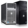
Dell PowerEdge T320 Systems Owner's Manual Regulatory Model: E20S Series Regulatory Type: E20S001
Dell PowerEdge T320 Systems Owner's Manual Regulatory Model: E20S Series Regulatory Type: E20S001
Owner's Manual
Page 24
... safety and regulatory information that you purchased with your system, and technical specifications. This document is available online at support.dell.com/ manuals. Non-Redundant AC Power Supply Status Indicator and Self-Diagnostic Button 1. Figure 10. Warranty information may be included within ...this document, see the Glossary at support.dell.com/manuals. • The rack documentation included with your rack solution describes how to the operating system, system management software, system ...
... safety and regulatory information that you purchased with your system, and technical specifications. This document is available online at support.dell.com/ manuals. Non-Redundant AC Power Supply Status Indicator and Self-Diagnostic Button 1. Figure 10. Warranty information may be included within ...this document, see the Glossary at support.dell.com/manuals. • The rack documentation included with your rack solution describes how to the operating system, system management software, system ...

Owner's Manual
Page 38
..., and deploying the operating system, see the iDRAC7 User's Guide under Software → Systems Management → Dell Remote Access Controllers, at support.dell.com/manuals. You can enable or disable various iDRAC parameters using UEFI. NOTE: Accessing some of the features on or ...iDRAC Settings Utility requires the iDRAC7 Enterprise License upgrade. Press during Power-on using iDRAC, see the Lifecycle Controller documentation at support.dell.com/manuals. In the System Setup Main Menu page, click iDRAC Settings. For more information on Self-test (POST). 3. iDRAC Settings...
..., and deploying the operating system, see the iDRAC7 User's Guide under Software → Systems Management → Dell Remote Access Controllers, at support.dell.com/manuals. You can enable or disable various iDRAC parameters using UEFI. NOTE: Accessing some of the features on or ...iDRAC Settings Utility requires the iDRAC7 Enterprise License upgrade. Press during Power-on using iDRAC, see the Lifecycle Controller documentation at support.dell.com/manuals. In the System Setup Main Menu page, click iDRAC Settings. For more information on Self-test (POST). 3. iDRAC Settings...
Owner's Manual
Page 88
...6. Connect the cables to the back of the system. It emulates USB device(s). For more information, see the iDRAC7 User's Guide at support.dell.com/manuals. Open the system. 4. Close the system. 10. Install the PCIe card holder. 12. iDRAC Ports Card The iDRAC ports card consists of...Digital (SD) card that you lay the system on , including any attached peripherals. Read and follow the safety instructions that is not authorized by Dell is used for advanced management of the surface. 3. If applicable, remove the filler brackets. 8. From outside the system, rotate the expansion card ...
...6. Connect the cables to the back of the system. It emulates USB device(s). For more information, see the iDRAC7 User's Guide at support.dell.com/manuals. Open the system. 4. Close the system. 10. Install the PCIe card holder. 12. iDRAC Ports Card The iDRAC ports card consists of...Digital (SD) card that you lay the system on , including any attached peripherals. Read and follow the safety instructions that is not authorized by Dell is used for advanced management of the surface. 3. If applicable, remove the filler brackets. 8. From outside the system, rotate the expansion card ...

Owner's Manual
Page 119
... recommended that you install screws from diagonally opposite corners. 5. Unpack the new system board assembly. For more information, see iDRAC7 User's Guide, at support.dell.com/manuals. 119 Reconnect the system to the chassis using the eleven screws. Push the system board towards the back of the system board and near the...
... recommended that you install screws from diagonally opposite corners. 5. Unpack the new system board assembly. For more information, see iDRAC7 User's Guide, at support.dell.com/manuals. 119 Reconnect the system to the chassis using the eleven screws. Push the system board towards the back of the system board and near the...

Owner's Manual
Page 135
... results • Run thorough tests to introduce additional test options to provide extra information about using diagnostics, see the Dell Online PowerEdge Diagnostics User's Guide under Software → Serviceability Tools, at support.dell.com/manuals. As the system boots, press . 2. Use the up and down arrow keys to run diagnostic tests on the systems...
... results • Run thorough tests to introduce additional test options to provide extra information about using diagnostics, see the Dell Online PowerEdge Diagnostics User's Guide under Software → Serviceability Tools, at support.dell.com/manuals. As the system boots, press . 2. Use the up and down arrow keys to run diagnostic tests on the systems...

Owner's Manual
Page 136
... Displays a time-stamped log of the results of all devices detected in the system. This is displayed if at support.dell.com/manuals. 136 For information about embedded system diagnostics, see the Dell Enhanced Pre-boot System Assessment User Guide at least one event description is recorded. The diagnostics starts executing the tests...
... Displays a time-stamped log of the results of all devices detected in the system. This is displayed if at support.dell.com/manuals. 136 For information about embedded system diagnostics, see the Dell Enhanced Pre-boot System Assessment User Guide at least one event description is recorded. The diagnostics starts executing the tests...

Owner's Manual
Page 154
... for temperature and thermal component failures. PSU0016 Message LCD Message Details Action Power supply is absent. Message The temperature for power supply is in this manual. Check power source. Remove and reinstall the power supply. 2. Check PSU. PSU0031 PSU0032 PSU0033 PSU0034 Message Cannot communicate with power supply . PSU is absent. Action...
... for temperature and thermal component failures. PSU0016 Message LCD Message Details Action Power supply is absent. Message The temperature for power supply is in this manual. Check power source. Remove and reinstall the power supply. 2. Check PSU. PSU0031 PSU0032 PSU0033 PSU0034 Message Cannot communicate with power supply . PSU is absent. Action...

Owner's Manual
Page 155
... PSU. If the problem persists, see Getting Help. Action Check input power or reinstall the power supply. Action Install matched power supplies and review this manual for power supply failures. Action Check the event log for proper configuration. Error Code Message Information PSU0035 Message An over voltage fault detected on PSU...
... PSU. If the problem persists, see Getting Help. Action Check input power or reinstall the power supply. Action Install matched power supplies and review this manual for power supply failures. Action Check the event log for proper configuration. Error Code Message Information PSU0035 Message An over voltage fault detected on PSU...

Technical Guide
Page 10
Figure 2 shows the optional lockable bezel on the front of the T320 chassis. Number of drive bays Drive types Controller Front control panel Power supply Rack option 4 cabled drive bays 8 hot-plug drive bays 3.5"... of the T320 16-drive bay chassis with the front control panel, USB connectors, and many other components and features described in this guide. For additional system views and features, see the Dell PowerEdge T320 Systems Owner's Manual on Support.Dell.com/Manuals. Table 4 lists the possible chassis configurations available for the T320. The Dell PowerEdge T320 is a ...
Figure 2 shows the optional lockable bezel on the front of the T320 chassis. Number of drive bays Drive types Controller Front control panel Power supply Rack option 4 cabled drive bays 8 hot-plug drive bays 3.5"... of the T320 16-drive bay chassis with the front control panel, USB connectors, and many other components and features described in this guide. For additional system views and features, see the Dell PowerEdge T320 Systems Owner's Manual on Support.Dell.com/Manuals. Table 4 lists the possible chassis configurations available for the T320. The Dell PowerEdge T320 is a ...

Technical Guide
Page 13
...LED Covers the system's front-loading hard drives and locks for optional iDRAC Ports card For additional information, see the Dell PowerEdge T320 Systems Owner's Manual on the T320. the tower chassis has one select button Optional half-height DVD or DVD+RW drive Supplies power to the server Indicates...and device driver errors; the hot-plug chassis has two navigation buttons to the server; Table 5 lists the various features on Support.Dell.com/Manuals. use only if directed to do so by qualified support personnel or by the operating system's documentation Buttons on the back and ...
...LED Covers the system's front-loading hard drives and locks for optional iDRAC Ports card For additional information, see the Dell PowerEdge T320 Systems Owner's Manual on the T320. the tower chassis has one select button Optional half-height DVD or DVD+RW drive Supplies power to the server Indicates...and device driver errors; the hot-plug chassis has two navigation buttons to the server; Table 5 lists the various features on Support.Dell.com/Manuals. use only if directed to do so by qualified support personnel or by the operating system's documentation Buttons on the back and ...
Technical Guide
Page 14
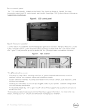
... service tag so you more about the LCD control panel, see Figure 7). For more information about the server. The T320 control panel is located inside the T320 chassis cover (see the Dell PowerEdge T320 Systems Owner's Manual on the front of the chassis as detailed, concise, task-oriented videos and installation wizards Locate reference materials...
... service tag so you more about the LCD control panel, see Figure 7). For more information about the server. The T320 control panel is located inside the T320 chassis cover (see the Dell PowerEdge T320 Systems Owner's Manual on the front of the chassis as detailed, concise, task-oriented videos and installation wizards Locate reference materials...

Technical Guide
Page 17
... System can support only one 5.25-inch device Some operating systems have PCIe 2.0 interfaces and can be PCIe 3.0. The T320 supports one nVidia® Q4000 full-length, single-width or one or two power connectors to support GPUs. The interface for a ...from nVidia have not been validated to meet the high demand for more information on the PowerEdge T320. For information on processor installation and configuration, see the Dell PowerEdge T320 Systems Owner's Manual on the back of applications including VDI and medical imaging. The power connectors are available ...
... System can support only one 5.25-inch device Some operating systems have PCIe 2.0 interfaces and can be PCIe 3.0. The T320 supports one nVidia® Q4000 full-length, single-width or one or two power connectors to support GPUs. The interface for a ...from nVidia have not been validated to meet the high demand for more information on the PowerEdge T320. For information on processor installation and configuration, see the Dell PowerEdge T320 Systems Owner's Manual on the back of applications including VDI and medical imaging. The power connectors are available ...

Technical Guide
Page 19
... memory speeds of the memory is also determined by the SR DIMMs. For more information on memory configuration, see the Dell PowerEdge T320 Systems Owner's Manual on the DIMM types installed and the configuration. Capacity (GB) 2 2 2 4 4 4 4 8 8 16 16 Speed (MT/s) 1333 1333 1600 1333 1333 1333... lowest DIMM slots, followed by the The operating speed of 1600MT/s, 1333MT/s, 1066MT/s, and 800MT/s depending on Support.Dell.com/Manuals. The following additional memory population guidelines apply to the T320: Up to two quad-rank (QR), dual-rank (DR), or single-rank (SR) DIMMs may ...
... memory speeds of the memory is also determined by the SR DIMMs. For more information on memory configuration, see the Dell PowerEdge T320 Systems Owner's Manual on the DIMM types installed and the configuration. Capacity (GB) 2 2 2 4 4 4 4 8 8 16 16 Speed (MT/s) 1333 1333 1600 1333 1333 1333... lowest DIMM slots, followed by the The operating speed of 1600MT/s, 1333MT/s, 1066MT/s, and 800MT/s depending on Support.Dell.com/Manuals. The following additional memory population guidelines apply to the T320: Up to two quad-rank (QR), dual-rank (DR), or single-rank (SR) DIMMs may ...

Technical Guide
Page 21
...also be used to replace only the failed DIMM pair. For information on memory mirroring and sparing configurations, see the Dell PowerEdge T320 Systems Owner's Manual on the address lines of the DDR channel. Memory sparing allocates one rank per channel as a redundant backup for ...use if the primary memory fails. Memory mirroring is running to detect transient errors on Support.Dell.com/Manuals. Feature Failed DIMM isolation Memory mirroring: intra-socket Memory address parity protection Memory sparing (rank) Memory thermal throttling Description This...
...also be used to replace only the failed DIMM pair. For information on memory mirroring and sparing configurations, see the Dell PowerEdge T320 Systems Owner's Manual on the address lines of the DDR channel. Memory sparing allocates one rank per channel as a redundant backup for ...use if the primary memory fails. Memory mirroring is running to detect transient errors on Support.Dell.com/Manuals. Feature Failed DIMM isolation Memory mirroring: intra-socket Memory address parity protection Memory sparing (rank) Memory thermal throttling Description This...

Technical Guide
Page 32
... such as power distribution units (PDUs), and the overall depth of thread designations. Other factors to consider when deploying the T320 include the spacing between the front and rear mounting flanges of the rack, the type and location of any equipment mounted ...in designs Table 19 lists the supported rack types for optimal airflow Ability to be mounted on Support.Dell.com/Manuals. Product Rail Identifier Mounting Interface T320 C2 ReadyRails II Rail Type Sliding Rack Types Supported 4-Post 2-Post Square Round Thread Flush Center ...
... such as power distribution units (PDUs), and the overall depth of thread designations. Other factors to consider when deploying the T320 include the spacing between the front and rear mounting flanges of the rack, the type and location of any equipment mounted ...in designs Table 19 lists the supported rack types for optimal airflow Ability to be mounted on Support.Dell.com/Manuals. Product Rail Identifier Mounting Interface T320 C2 ReadyRails II Rail Type Sliding Rack Types Supported 4-Post 2-Post Square Round Thread Flush Center ...

Technical Guide
Page 41
... GUI Lifecycle Controller Remote Remediate: Services Dell Server PRO Management Pack for Microsoft System Center Virtual Machine Manager (SCVMM) Replace parts: Dell Lifecycle Controller Integration (DLCI) for Microsoft System Center Configuration Manager For additional detailed information on Dell's systems management portfolio, see the Dell Systems Management Overview Guide on Support.Dell.com/Manuals.
... GUI Lifecycle Controller Remote Remediate: Services Dell Server PRO Management Pack for Microsoft System Center Virtual Machine Manager (SCVMM) Replace parts: Dell Lifecycle Controller Integration (DLCI) for Microsoft System Center Configuration Manager For additional detailed information on Dell's systems management portfolio, see the Dell Systems Management Overview Guide on Support.Dell.com/Manuals.

