Getting Started Guide
Page 6
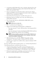
... four internal, 3.5-inch, Serial-Attached SCSI (SAS) hard drives with integrated drive controllers. - The following software is supported only when SATA or SAS drives are data only. • One 3.5-inch drive bay for floppy drive. • Support for remote systems management. NOTE:... see "Technical Specifications". The systems management circuitry works in the following internal hard-drive configurations: - NOTE: DVD devices are connected to four internal, 3.5-inch, SATA hard drives with an optional SAS controller card or backplane. Either option requires the backplane...
... four internal, 3.5-inch, Serial-Attached SCSI (SAS) hard drives with integrated drive controllers. - The following software is supported only when SATA or SAS drives are data only. • One 3.5-inch drive bay for floppy drive. • Support for remote systems management. NOTE:... see "Technical Specifications". The systems management circuitry works in the following internal hard-drive configurations: - NOTE: DVD devices are connected to four internal, 3.5-inch, SATA hard drives with an optional SAS controller card or backplane. Either option requires the backplane...
Getting Started Guide
Page 13
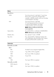
One optional 3.5-inch, 1.44-MB One optional SATA or SCSI tape backup unit in the optical drive bay. One SATA DVD or combination CD-RW/DVD NOTE: DVD devices are data only. Drives Hard Drives SATA SAS Optical drive Diskette drive Tape drive Connectors Externally accessible Back NIC Serial USB Video Front USB Internally accessible SATA channels USB...
One optional 3.5-inch, 1.44-MB One optional SATA or SCSI tape backup unit in the optical drive bay. One SATA DVD or combination CD-RW/DVD NOTE: DVD devices are data only. Drives Hard Drives SATA SAS Optical drive Diskette drive Tape drive Connectors Externally accessible Back NIC Serial USB Video Front USB Internally accessible SATA channels USB...

Hardware Owner's Manual (PDF)
Page 5
... a Non-Redundant Power Supply. . . . . 77 Hard Drives 77 Removing a Hot-Pluggable Hard Drive 77 Installing a Hot-Pluggable Hard Drive 78 Removing a Cabled Hard Drive 80 Installing a Cabled Hard Drive 82 Configuring the Boot Device 84 Diskette Drive (Optional 84 Removing the Diskette Drive 84 Installing a Diskette Drive 86 Optical and Tape Drives 88 Removing an Optical or Tape Drive 88 Installing an Optical or Tape...
... a Non-Redundant Power Supply. . . . . 77 Hard Drives 77 Removing a Hot-Pluggable Hard Drive 77 Installing a Hot-Pluggable Hard Drive 78 Removing a Cabled Hard Drive 80 Installing a Cabled Hard Drive 82 Configuring the Boot Device 84 Diskette Drive (Optional 84 Removing the Diskette Drive 84 Installing a Diskette Drive 86 Optical and Tape Drives 88 Removing an Optical or Tape Drive 88 Installing an Optical or Tape...
Hardware Owner's Manual (PDF)
Page 8
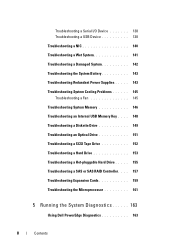
... Memory 146 Troubleshooting an Internal USB Memory Key . . . . 148 Troubleshooting a Diskette Drive 149 Troubleshooting an Optical Drive 151 Troubleshooting a SCSI Tape Drive 152 Troubleshooting a Hard Drive 153 Troubleshooting a Hot-pluggable Hard Drive . . . . . 155 Troubleshooting a SAS or SAS RAID Controller. . . . 157 Troubleshooting Expansion Cards 159 Troubleshooting the Microprocessor 161 5 Running the System Diagnostics 163 Using Dell PowerEdge Diagnostics 163 8 Contents
... Memory 146 Troubleshooting an Internal USB Memory Key . . . . 148 Troubleshooting a Diskette Drive 149 Troubleshooting an Optical Drive 151 Troubleshooting a SCSI Tape Drive 152 Troubleshooting a Hard Drive 153 Troubleshooting a Hot-pluggable Hard Drive . . . . . 155 Troubleshooting a SAS or SAS RAID Controller. . . . 157 Troubleshooting Expansion Cards 159 Troubleshooting the Microprocessor 161 5 Running the System Diagnostics 163 Using Dell PowerEdge Diagnostics 163 8 Contents

Hardware Owner's Manual (PDF)
Page 25
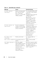
...component that resides in PCIe configuration space "Troubleshooting at bus ##, device ##, Expansion Cards" on a component that hard drive Hard Drive" on setup and use of BMC. See "Troubleshooting a Hard Drive" on page 175. E1A15 SAS Cable B SAS cable B is missing or bad. About Your System 25 page...has See "Troubleshooting a determined that resides the problem persists, see "Getting Help" on page 153. E1812 HDD ## Removed The specified hard drive has Information only. E1A14 SAS Cable A SAS cable A is missing or bad. Reseat the cable. If the problem persists, replace the...
...component that resides in PCIe configuration space "Troubleshooting at bus ##, device ##, Expansion Cards" on a component that hard drive Hard Drive" on setup and use of BMC. See "Troubleshooting a Hard Drive" on page 175. E1A15 SAS Cable B SAS cable B is missing or bad. About Your System 25 page...has See "Troubleshooting a determined that resides the problem persists, see "Getting Help" on page 153. E1812 HDD ## Removed The specified hard drive has Information only. E1A14 SAS Cable A SAS cable A is missing or bad. Reseat the cable. If the problem persists, replace the...
Hardware Owner's Manual (PDF)
Page 34
... BIOS failed to an "Troubleshooting Expansion expansion card is faulty or improperly installed. 34 About Your System unseated; If the problem drive, or hard-drive persists, see "Using the System Setup Program" on hard drive. Not a boot diskette No operating system on page 153. A cable to install PCIe device BIOS Reseat the expansion card(s) (Option...
... BIOS failed to an "Troubleshooting Expansion expansion card is faulty or improperly installed. 34 About Your System unseated; If the problem drive, or hard-drive persists, see "Using the System Setup Program" on hard drive. Not a boot diskette No operating system on page 153. A cable to install PCIe device BIOS Reseat the expansion card(s) (Option...

Hardware Owner's Manual (PDF)
Page 35
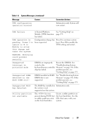
...Requested sector not found The operating system Replace the USB medium or cannot read from the hard device. Ensure that the USB drive or USB device, the or hard drive cables are system could not find a properly connected. Remote Configuration request. About Your System ...35 Reseat the PCIe card in Configuration Error initializing PCIe device; Install the NVRAM_CLR jumper and reboot the system. "Troubleshooting a Hard Drive" on page 95). Reseat the expansion card(s) and expansion card cables. System Messages (continued) Message Causes Corrective Actions PCIe Fatal Error...
...Requested sector not found The operating system Replace the USB medium or cannot read from the hard device. Ensure that the USB drive or USB device, the or hard drive cables are system could not find a properly connected. Remote Configuration request. About Your System ...35 Reseat the PCIe card in Configuration Error initializing PCIe device; Install the NVRAM_CLR jumper and reboot the system. "Troubleshooting a Hard Drive" on page 95). Reseat the expansion card(s) and expansion card cables. System Messages (continued) Message Causes Corrective Actions PCIe Fatal Error...

Hardware Owner's Manual (PDF)
Page 36
... in your system. Timer chip counter Faulty system board. 2 failed Corrective Actions See "Troubleshooting a Hard Drive" on page 143. See "Troubleshooting a USB Device" on page 138 or "Troubleshooting a Hard Drive" on page 146). If memory has not been added or removed, check the SEL to determine if ...Your System See "Getting Help" on in your system. System Messages (continued) Message SATA PORT n drive not found Causes SATA port x was not found Seek error Seek operation failed Faulty hard drive, USB device, or USB medium. The amount of -day not set Incorrect time or date - ...
... in your system. Timer chip counter Faulty system board. 2 failed Corrective Actions See "Troubleshooting a Hard Drive" on page 143. See "Troubleshooting a USB Device" on page 138 or "Troubleshooting a Hard Drive" on page 146). If memory has not been added or removed, check the SEL to determine if ...Your System See "Getting Help" on in your system. System Messages (continued) Message SATA PORT n drive not found Causes SATA port x was not found Seek error Seek operation failed Faulty hard drive, USB device, or USB medium. The amount of -day not set Incorrect time or date - ...
Hardware Owner's Manual (PDF)
Page 37
... M to allow this system. Unsupported DIMM detected in Information only. system. TPM failure A Trusted Platform See "Getting Help" on pressed during POST, but the boot hard drive. has failed. Unexpected interrupt in RAID DIMM slot is pending. See "Troubleshooting System Memory" on page 146. Unsupported RAID key detected. If the problem persists... and restart. If the chip has failed. boot. The RAID key installed in the RAID DIMM slot! the system is not supported on the boot hard drive.
... M to allow this system. Unsupported DIMM detected in Information only. system. TPM failure A Trusted Platform See "Getting Help" on pressed during POST, but the boot hard drive. has failed. Unexpected interrupt in RAID DIMM slot is pending. See "Troubleshooting System Memory" on page 146. Unsupported RAID key detected. If the problem persists... and restart. If the chip has failed. boot. The RAID key installed in the RAID DIMM slot! the system is not supported on the boot hard drive.

Hardware Owner's Manual (PDF)
Page 39
...information on support.dell.com Invalid memory Ensure that you format a hard drive, a message will run but at a reduced valid configuration (see functionality. "Memory Module Installation Guidelines" on selected drive Faulty USB device, USB medium, optical drive assembly, hard drive, or hard-drive subsystem. Warning Messages...Device" on page 138, "Troubleshooting an Internal USB Memory Key" on page 148, or "Troubleshooting a Hard Drive" on the hard drive. NOTE: Warning messages are installed in this table, see "Troubleshooting System Memory" on page 177. About Your System 39
...information on support.dell.com Invalid memory Ensure that you format a hard drive, a message will run but at a reduced valid configuration (see functionality. "Memory Module Installation Guidelines" on selected drive Faulty USB device, USB medium, optical drive assembly, hard drive, or hard-drive subsystem. Warning Messages...Device" on page 138, "Troubleshooting an Internal USB Memory Key" on page 148, or "Troubleshooting a Hard Drive" on the hard drive. NOTE: Warning messages are installed in this table, see "Troubleshooting System Memory" on page 177. About Your System 39

Hardware Owner's Manual (PDF)
Page 44
... the system's internal clock. Available options can include the diskette drive, CD drive, hard drives, and network. Auto automatically chooses an emulation type. If you have installed a RAC, additional options such as hard drive, CD drive, or DVD drive) (see Table 2-4). See support.dell.com for a USB flash drive. Enables or disables the Boot Sequence Retry feature. Determines the order...
... the system's internal clock. Available options can include the diskette drive, CD drive, hard drives, and network. Auto automatically chooses an emulation type. If you have installed a RAC, additional options such as hard drive, CD drive, or DVD drive) (see Table 2-4). See support.dell.com for a USB flash drive. Enables or disables the Boot Sequence Retry feature. Determines the order...
Hardware Owner's Manual (PDF)
Page 59
... components: • Front bezel • System cover • EMI fillers • Processor airflow shroud • Power supplies and power distribution board • Hard drives • Diskette drive • Optical and tape drives • Expansion cards • SAS controller card • RAID battery • RAC card • Internal USB memory key connector • System fan...
... components: • Front bezel • System cover • EMI fillers • Processor airflow shroud • Power supplies and power distribution board • Hard drives • Diskette drive • Optical and tape drives • Expansion cards • SAS controller card • RAID battery • RAC card • Internal USB memory key connector • System fan...

Hardware Owner's Manual (PDF)
Page 62
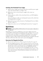
... of your system supports a single processor, five expansion cards, and six memory modules. Power is required for four SAS or SATA hard drives, cabled or hot-pluggable. Front Bezel The front bezel covers the front of redundant power supplies or a single non-redundant power supply... front bezel must first be turned off and placed in the orientation shown in Figure 3-1. 62 Installing System Components Internal hard drive bays offer space for SAS hard drives. In order to remove or install any other system component(s), the system should be removed. NOTE: If you are ...
... of your system supports a single processor, five expansion cards, and six memory modules. Power is required for four SAS or SATA hard drives, cabled or hot-pluggable. Front Bezel The front bezel covers the front of redundant power supplies or a single non-redundant power supply... front bezel must first be turned off and placed in the orientation shown in Figure 3-1. 62 Installing System Components Internal hard drive bays offer space for SAS hard drives. In order to remove or install any other system component(s), the system should be removed. NOTE: If you are ...
Hardware Owner's Manual (PDF)
Page 77
... ready for removal and wait until the power supply release tab snaps into the back of the chassis until the hard drive indicators on the front of the drive carrier signal that all power cables to prevent the cables from becoming pinched or crimped. 4 Replace the processor airflow ... Shroud" on page 72). 5 Replace the system cover (see "Installing the System Cover" on page 67). Hard drives installed in the same system configuration is not supported. Removing a Hot-Pluggable Hard Drive 1 Remove the front bezel (see "Removing the Front Bezel" on page 63). 2 From the RAID management software...
... ready for removal and wait until the power supply release tab snaps into the back of the chassis until the hard drive indicators on the front of the drive carrier signal that all power cables to prevent the cables from becoming pinched or crimped. 4 Replace the processor airflow ... Shroud" on page 72). 5 Replace the system cover (see "Installing the System Cover" on page 67). Hard drives installed in the same system configuration is not supported. Removing a Hot-Pluggable Hard Drive 1 Remove the front bezel (see "Removing the Front Bezel" on page 63). 2 From the RAID management software...

Hardware Owner's Manual (PDF)
Page 78
..., then rotate the handle down to release the drive. 4 Slide the hard drive out of the system. Figure 3-11. Removing and Installing a Hot-Pluggable Hard Drive 2 1 3 1 hard drive carrier handle 3 tabs 2 hard drive bays (4) Installing a Hot-Pluggable Hard Drive NOTICE: It is recommended that you are not replacing the hard drive, remove the drive from the drive carrier (see Figure 3-12) and insert the empty...
..., then rotate the handle down to release the drive. 4 Slide the hard drive out of the system. Figure 3-11. Removing and Installing a Hot-Pluggable Hard Drive 2 1 3 1 hard drive carrier handle 3 tabs 2 hard drive bays (4) Installing a Hot-Pluggable Hard Drive NOTICE: It is recommended that you are not replacing the hard drive, remove the drive from the drive carrier (see Figure 3-12) and insert the empty...

Hardware Owner's Manual (PDF)
Page 79
... "Removing the Front Bezel" on page 63). 3 Remove either the existing hard drive, if applicable, or the hard drive carrier (see "Diskette Drive (Optional)" on page 84). 4 Install the hard drive carrier on the hard drive with the connector end of the drive at the rear. See Figure 3-12. a Insert the hard drive into the hard-drive carrier with the rear set of the...
... "Removing the Front Bezel" on page 63). 3 Remove either the existing hard drive, if applicable, or the hard drive carrier (see "Diskette Drive (Optional)" on page 84). 4 Install the hard drive carrier on the hard drive with the connector end of the drive at the rear. See Figure 3-12. a Insert the hard drive into the hard-drive carrier with the rear set of the...

Hardware Owner's Manual (PDF)
Page 80
..."Removing the System Cover" on page 64). Removing and Installing a Hard Drive Carrier 1 2 3 4 1 screws (4) 3 hard drive 2 hard drive carrier 4 SAS mounting hole 5 With the handle on the hard drive carrier open, slide the hard drive into the drive bay until the carrier contacts the backplane (see Figure 3-11). ... (see your Product Information Guide for complete information about safety precautions, working inside the system. Removing a Cabled Hard Drive CAUTION: Only trained service technicians are authorized to remove the system cover and access any procedure, see "Installing the...
..."Removing the System Cover" on page 64). Removing and Installing a Hard Drive Carrier 1 2 3 4 1 screws (4) 3 hard drive 2 hard drive carrier 4 SAS mounting hole 5 With the handle on the hard drive carrier open, slide the hard drive into the drive bay until the carrier contacts the backplane (see Figure 3-11). ... (see your Product Information Guide for complete information about safety precautions, working inside the system. Removing a Cabled Hard Drive CAUTION: Only trained service technicians are authorized to remove the system cover and access any procedure, see "Installing the...

Hardware Owner's Manual (PDF)
Page 81
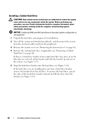
... and Installing a Cabled Hard Drive 2 3 1 4 1 hard drive 3 power cable 2 data cable 4 blue tabs (2) NOTE: If you are not replacing the hard drive, remove the drive from the hard drive in the drive bay. 4 Press in on the blue tabs on page 67). Installing System Components 81 3 Disconnect the data cable and the power cable from the drive bracket (see Figure 3-14...
... and Installing a Cabled Hard Drive 2 3 1 4 1 hard drive 3 power cable 2 data cable 4 blue tabs (2) NOTE: If you are not replacing the hard drive, remove the drive from the hard drive in the drive bay. 4 Press in on the blue tabs on page 67). Installing System Components 81 3 Disconnect the data cable and the power cable from the drive bracket (see Figure 3-14...
Hardware Owner's Manual (PDF)
Page 82
... and slide the bracket up and out of the system. (see Figure 3-13). 5 Snap the hard drive bracket onto the hard drive (see Figure 3-14). To remove the hard drive, spread the sides of the hard-drive bracket outward and lift the drive from the bracket (see your Product Information Guide for installation. 2 Turn off the system and attached...
... and slide the bracket up and out of the system. (see Figure 3-13). 5 Snap the hard drive bracket onto the hard drive (see Figure 3-14). To remove the hard drive, spread the sides of the hard-drive bracket outward and lift the drive from the bracket (see your Product Information Guide for installation. 2 Turn off the system and attached...
Hardware Owner's Manual (PDF)
Page 83
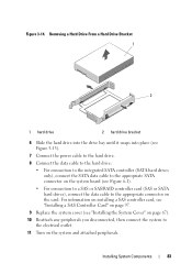
Removing a Hard Drive From a Hard Drive Bracket 1 2 1 hard drive 2 hard drive bracket 6 Slide the hard drive into the drive bay until it snaps into place (see Figure 3-13). 7 Connect the power cable to the hard drive. 8 Connect the data cable to the hard drive: • For connection to the integrated SATA controller (SATA hard drives only), connect... system cover (see Figure 6-1). • For connection to a SAS or SAS/RAID controller card (SAS or SATA hard drives), connect the data cable to the electrical outlet. 11 Turn on the card. Figure 3-14. Installing System Components 83
Removing a Hard Drive From a Hard Drive Bracket 1 2 1 hard drive 2 hard drive bracket 6 Slide the hard drive into the drive bay until it snaps into place (see Figure 3-13). 7 Connect the power cable to the hard drive. 8 Connect the data cable to the hard drive: • For connection to the integrated SATA controller (SATA hard drives only), connect... system cover (see Figure 6-1). • For connection to a SAS or SAS/RAID controller card (SAS or SATA hard drives), connect the data cable to the electrical outlet. 11 Turn on the card. Figure 3-14. Installing System Components 83


