Getting Started Guide
Page 5
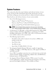
... USB 2.0-compliant connectors (two on the front, four on the system board. • The following processors: - It also provides information about other documents you have a DRAC card, install it in six module sockets on the back, and one internal) capable of supporting a diskette drive, CD-ROM drive, keyboard, mouse, or USB...
... USB 2.0-compliant connectors (two on the front, four on the system board. • The following processors: - It also provides information about other documents you have a DRAC card, install it in six module sockets on the back, and one internal) capable of supporting a diskette drive, CD-ROM drive, keyboard, mouse, or USB...
Getting Started Guide
Page 6
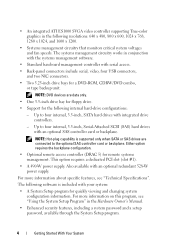
.... • One 3.5-inch drive bay for floppy drive. • Support for remote systems management. Either option requires the backplane configuration. • Optional remote access controller (DRAC 5) for the following internal hard-drive configurations: - For more information on this program, see "Technical Specifications". The following resolutions: 640 x 480, 800 x 600, 1024 x 768...
.... • One 3.5-inch drive bay for floppy drive. • Support for remote systems management. Either option requires the backplane configuration. • Optional remote access controller (DRAC 5) for the following internal hard-drive configurations: - For more information on this program, see "Technical Specifications". The following resolutions: 640 x 480, 800 x 600, 1024 x 768...
Hardware Owner's Manual (PDF)
Page 27
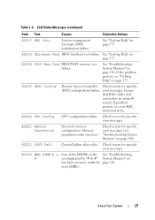
E201E POST Mem Test BIOS POST memory test failure. E201F DRAC Config Remote Access Controller Check screen for specific error messages (see "Troubleshooting System Memory" on page 146. Ensure that RAC cables and connectors are properly ...
E201E POST Mem Test BIOS POST memory test failure. E201F DRAC Config Remote Access Controller Check screen for specific error messages (see "Troubleshooting System Memory" on page 146. Ensure that RAC cables and connectors are properly ...
Hardware Owner's Manual (PDF)
Page 168
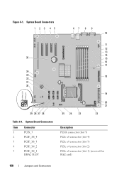
System Board Connectors 1 2 3 45 67 8 9 10 35 34 33 32 31 30 29 28 27 26 Table 6-1. System Board Connectors Item Connector 1 PCIX_5 2 PCIE_X8_4 3 PCIE_X8_3 4 PCIE_X4_2 5 PCIE_X4_1 DRAC SLOT 11 12 13 14 15 16 17 18 25 24 23 19 20 21 22 Description PCI-X connector (slot 5) PCIe x8 connector (slot 4) PCIe x8 connector (slot 3) PCIe x4 connector (slot 2) PCIe x8 connector (slot 1) (reserved for RAC card) 168 Jumpers and Connectors Figure 6-1.
System Board Connectors 1 2 3 45 67 8 9 10 35 34 33 32 31 30 29 28 27 26 Table 6-1. System Board Connectors Item Connector 1 PCIX_5 2 PCIE_X8_4 3 PCIE_X8_3 4 PCIE_X4_2 5 PCIE_X4_1 DRAC SLOT 11 12 13 14 15 16 17 18 25 24 23 19 20 21 22 Description PCI-X connector (slot 5) PCIe x8 connector (slot 4) PCIe x8 connector (slot 3) PCIe x4 connector (slot 2) PCIe x8 connector (slot 1) (reserved for RAC card) 168 Jumpers and Connectors Figure 6-1.


