Installation and Troubleshooting Guide (.htm)
Page 5
Contents Safety Instructions 5 SAFETY: Rack Mounting of Systems 5 Installation Instructions 6 Before You Begin 7 Installation Tasks 8 Recommended Tools and Supplies 8 RapidRails Rack Kit Contents 8 VersaRails Rack Kit Contents 9 Marking the Rack 11 Installing the RapidRails Slide Assemblies 13 Installing the VersaRails Slide Assemblies 15 Installing the System in the Rack 17 Installing the Cable Tray and Cable-Management Arm 19 Attaching the Cable Tray to the System 19 Securing the Cable-Management Arm 19 Routing Cables 21 Contents 3
Contents Safety Instructions 5 SAFETY: Rack Mounting of Systems 5 Installation Instructions 6 Before You Begin 7 Installation Tasks 8 Recommended Tools and Supplies 8 RapidRails Rack Kit Contents 8 VersaRails Rack Kit Contents 9 Marking the Rack 11 Installing the RapidRails Slide Assemblies 13 Installing the VersaRails Slide Assemblies 15 Installing the System in the Rack 17 Installing the Cable Tray and Cable-Management Arm 19 Attaching the Cable Tray to the System 19 Securing the Cable-Management Arm 19 Routing Cables 21 Contents 3
Installation and Troubleshooting Guide (.htm)
Page 10
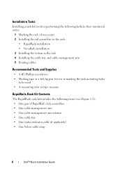
... assemblies in the rack: • RapidRails installation • VersaRails installation 3 Installing the system in the rack 4 Installing the cable tray and cable-management arm 5 Routing cables Recommended Tools and Supplies • A #2 Phillips screwdriver • Masking tape or a felt-tip pen, for use in... (see Figure 1-1): • One pair of RapidRails slide assemblies • One cable-management arm • One cable-management arm retainer • One cable tray • One status indicator cable (if applicable) • One Velcro cable strap 8 Dell™ Rack Installation Guide
... assemblies in the rack: • RapidRails installation • VersaRails installation 3 Installing the system in the rack 4 Installing the cable tray and cable-management arm 5 Routing cables Recommended Tools and Supplies • A #2 Phillips screwdriver • Masking tape or a felt-tip pen, for use in... (see Figure 1-1): • One pair of RapidRails slide assemblies • One cable-management arm • One cable-management arm retainer • One cable tray • One status indicator cable (if applicable) • One Velcro cable strap 8 Dell™ Rack Installation Guide
Installation and Troubleshooting Guide (.htm)
Page 11
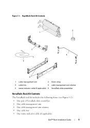
RapidRails Rack Kit Contents 2 1 3 4 5 6 1 cable-management arm 2 Velcro strap 3 cable tray 4 cable management arm retainer 5 status indicator cable (if applicable) 6 VersaRails slide assemblies VersaRails Rack Kit Contents The VersaRails rack kit includes the following items (see Figure 1-2): • One pair of VersaRails slide assemblies • One cable-management arm • One cable-management arm retainer • One cable tray • One status indicator cable (if applicable) Dell™ Rack Installation Guide 9 Figure 1-1.
RapidRails Rack Kit Contents 2 1 3 4 5 6 1 cable-management arm 2 Velcro strap 3 cable tray 4 cable management arm retainer 5 status indicator cable (if applicable) 6 VersaRails slide assemblies VersaRails Rack Kit Contents The VersaRails rack kit includes the following items (see Figure 1-2): • One pair of VersaRails slide assemblies • One cable-management arm • One cable-management arm retainer • One cable tray • One status indicator cable (if applicable) Dell™ Rack Installation Guide 9 Figure 1-1.
Installation and Troubleshooting Guide (.htm)
Page 12
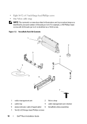
... threads per inch is identified as a 10-32 screw. Figure 1-2. For example, a #10 Phillips-head screw with 32 threads per inch. VersaRails Rack Kit Contents 1 2 3 4 5 6 7 1 cable-management arm 2 Velcro strap 3 cable tray 4 cable management arm retainer 5 status indicator cable (if applicable) 6 VersaRails slide assemblies 7 Ten 32 x 0.5 flange-head Phillips screws 10 Dell™ Rack Installation Guide
... threads per inch is identified as a 10-32 screw. Figure 1-2. For example, a #10 Phillips-head screw with 32 threads per inch. VersaRails Rack Kit Contents 1 2 3 4 5 6 7 1 cable-management arm 2 Velcro strap 3 cable tray 4 cable management arm retainer 5 status indicator cable (if applicable) 6 VersaRails slide assemblies 7 Ten 32 x 0.5 flange-head Phillips screws 10 Dell™ Rack Installation Guide
Installation and Troubleshooting Guide (.htm)
Page 17
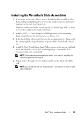
... Phillips screws in the second and third holes (middle holes) of the back mounting flange to secure the slide assembly to the back vertical rail. Dell™ Rack Installation Guide 15 NOTE: Ensure that its mounting-bracket flange fits between the marks on the front vertical rail. 2 Install a 10-32 x 0.5-inch... at the same vertical position on both sides of the rack. NOTE: The top and bottom flange holes will be used later for installing the cable-management arm retainer. 5 Repeat steps 1 through 4 for the slide assembly on the other side of the rack.
... Phillips screws in the second and third holes (middle holes) of the back mounting flange to secure the slide assembly to the back vertical rail. Dell™ Rack Installation Guide 15 NOTE: Ensure that its mounting-bracket flange fits between the marks on the front vertical rail. 2 Install a 10-32 x 0.5-inch... at the same vertical position on both sides of the rack. NOTE: The top and bottom flange holes will be used later for installing the cable-management arm retainer. 5 Repeat steps 1 through 4 for the slide assembly on the other side of the rack.
Installation and Troubleshooting Guide (.htm)
Page 21
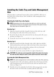
...tabs along the sides of the system chassis. Lift the system only by the chassis edges. Securing the Cable-Management Arm NOTE: The cable-management arm can be installed on either side of the cable tray. 1 Facing the back of the rack cabinet, push the tab on the front end of ...cable trays are illustrated in two phases. Do not grasp the cable tray when lifting the system. First, install the cable tray to the System NOTE: Depending on the cable tray that ships with the two captive thumbscrews. Dell™ Rack Installation Guide 19 Installing the Cable Tray and Cable-Management Arm...
...tabs along the sides of the system chassis. Lift the system only by the chassis edges. Securing the Cable-Management Arm NOTE: The cable-management arm can be installed on either side of the cable tray. 1 Facing the back of the rack cabinet, push the tab on the front end of ...cable trays are illustrated in two phases. Do not grasp the cable tray when lifting the system. First, install the cable tray to the System NOTE: Depending on the cable tray that ships with the two captive thumbscrews. Dell™ Rack Installation Guide 19 Installing the Cable Tray and Cable-Management Arm...

Installation and Troubleshooting Guide (.htm)
Page 22
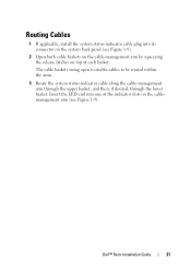
Figure 1-8. Installing the Cable-Management Arm 3 2 1 back of system 4 back of rack 5 6 Mounting Type I 7 8 9 Mounting Type II 1 latch on cable tray 3 cable-management arm 5 captive thumbscrews (4) 7 Velcro strap 9 mounting tabs (2) 2 tabs 4 cable-management retainer 6 captive thumbscrews (2) 8 formed metal tabs NOTE: Figure 1-8 illustrates both rack rail types that demonstrate how to connect the rack to your system. 20 Dell™ Rack Installation Guide
Figure 1-8. Installing the Cable-Management Arm 3 2 1 back of system 4 back of rack 5 6 Mounting Type I 7 8 9 Mounting Type II 1 latch on cable tray 3 cable-management arm 5 captive thumbscrews (4) 7 Velcro strap 9 mounting tabs (2) 2 tabs 4 cable-management retainer 6 captive thumbscrews (2) 8 formed metal tabs NOTE: Figure 1-8 illustrates both rack rail types that demonstrate how to connect the rack to your system. 20 Dell™ Rack Installation Guide
Installation and Troubleshooting Guide (.htm)
Page 23
... into its connector on the system back panel (see Figure 1-9). 2 Open both cable baskets on the cable-management arm by squeezing the release latches on top of the indicator slots on the cablemanagement arm (see Figure 1-9). Dell™ Rack Installation Guide 21 Routing Cables 1 If applicable, install the system status-indicator cable plug into one of each basket.
... into its connector on the system back panel (see Figure 1-9). 2 Open both cable baskets on the cable-management arm by squeezing the release latches on top of the indicator slots on the cablemanagement arm (see Figure 1-9). Dell™ Rack Installation Guide 21 Routing Cables 1 If applicable, install the system status-indicator cable plug into one of each basket.

Installation and Troubleshooting Guide (.htm)
Page 25
... surface of the cable tray using the Velcro straps, then route the cables along the bend to where the cablemanagement arm attaches to the cable tray, and secure the cables with the vertical Velcro strap (see Figure 1-10). 6 Route the cables along the cable-management arm through both cable baskets, starting with... cable slack as needed at the hinge position. 8 Use the Velcro strap that ships with your system to tightly secure the cable bundle to the cable basket elbow. 9 Close the cable baskets. 10 Unscrew the thumbscrews that secure the front of the system to the front vertical rail. Dell&#...
... surface of the cable tray using the Velcro straps, then route the cables along the bend to where the cablemanagement arm attaches to the cable tray, and secure the cables with the vertical Velcro strap (see Figure 1-10). 6 Route the cables along the cable-management arm through both cable baskets, starting with... cable slack as needed at the hinge position. 8 Use the Velcro strap that ships with your system to tightly secure the cable bundle to the cable basket elbow. 9 Close the cable baskets. 10 Unscrew the thumbscrews that secure the front of the system to the front vertical rail. Dell&#...

Installation and Troubleshooting Guide (.htm)
Page 26
Routing Cables on the Cable-Management Arm 1 2 1 cable tray Velcro strap (6) 2 CMA Velcro strap 24 Dell™ Rack Installation Guide Figure 1-10.
Routing Cables on the Cable-Management Arm 1 2 1 cable tray Velcro strap (6) 2 CMA Velcro strap 24 Dell™ Rack Installation Guide Figure 1-10.

Installation and Troubleshooting Guide (.htm)
Page 27
... system in the extended position. Dell™ Rack Installation Guide 25 NOTE: If you pull the system out to the back of the cable-management arm. Adjust the cable positioning inside the cable baskets as needed. NOTE: Be sure to route the system cables under the retainer bar so that the cables are routed correctly and do not... release the lock, press the slide release latch on the side of the slide and then slide the system into the rack. 12 Secure the cable-management arm retainer to its furthest extension, the slide assemblies will lock in and out of the rack to verify that the...
... system in the extended position. Dell™ Rack Installation Guide 25 NOTE: If you pull the system out to the back of the cable-management arm. Adjust the cable positioning inside the cable baskets as needed. NOTE: Be sure to route the system cables under the retainer bar so that the cables are routed correctly and do not... release the lock, press the slide release latch on the side of the slide and then slide the system into the rack. 12 Secure the cable-management arm retainer to its furthest extension, the slide assemblies will lock in and out of the rack to verify that the...
Hardware Owner's Manual (PDF)
Page 71
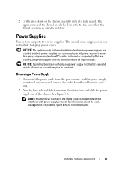
... components (such as a redundant, hot-plug power source. The second power supply serves as PCI cards) not tested or supported by Dell are connected to unlatch and lift the cable management arm if it is correctly installed. See Figure 3-6. 2 Gently press down on the shroud assembly until it interferes with only one power supply...
... components (such as a redundant, hot-plug power source. The second power supply serves as PCI cards) not tested or supported by Dell are connected to unlatch and lift the cable management arm if it is correctly installed. See Figure 3-6. 2 Gently press down on the shroud assembly until it interferes with only one power supply...
Hardware Owner's Manual (PDF)
Page 72
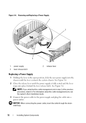
... latch. See Figure 3-6. 2 Close the release lever until the lever contacts the system chassis. NOTE: If you unlatched the cable management arm in the open position, slide the new power supply into the chassis until the power supply is fully seated and the lever snaps... into a power outlet. See Figure 3-6. NOTICE: When connecting the power cable, insert the cable through the strainrelief loop. 72 Installing System Components Figure 3-6. Removing and Replacing a Power Supply 1 2 3 1 power supply 3 lever release ...
... latch. See Figure 3-6. 2 Close the release lever until the lever contacts the system chassis. NOTE: If you unlatched the cable management arm in the open position, slide the new power supply into the chassis until the power supply is fully seated and the lever snaps... into a power outlet. See Figure 3-6. NOTICE: When connecting the power cable, insert the cable through the strainrelief loop. 72 Installing System Components Figure 3-6. Removing and Replacing a Power Supply 1 2 3 1 power supply 3 lever release ...


