
Glossary
Page 2
.... A method of the system that allows the processor to interface correctly with controllers for the serial ports on your system. driver - Digital versatile disc or digital video disc. EMI - Electromagnetic interference. Embedded remote access. ESD - The part of automatically... of data between the processor and memory or between the expansion bus and a peripheral. 2 Dynamic Host Configuration Protocol. DVD - See device driver. See also memory module. Electrostatic discharge. Double-data rate. DHCP - ESM - expansion bus - expansion card - A chip that plugs...
.... A method of the system that allows the processor to interface correctly with controllers for the serial ports on your system. driver - Digital versatile disc or digital video disc. EMI - Electromagnetic interference. Embedded remote access. ESD - The part of automatically... of data between the processor and memory or between the expansion bus and a peripheral. 2 Dynamic Host Configuration Protocol. DVD - See device driver. See also memory module. Electrostatic discharge. Double-data rate. DHCP - ESM - expansion bus - expansion card - A chip that plugs...
Glossary
Page 9
... CIM Object Manager services. Watt-hour(s). V - VDC - video memory - utility - video resolution - To display a program at a specific graphics resolution, you must install the appropriate video drivers and your system's RAM. Watt(s). Most VGA and SVGA video adapters include memory chips in combination with the appropriate video...
... CIM Object Manager services. Watt-hour(s). V - VDC - video memory - utility - video resolution - To display a program at a specific graphics resolution, you must install the appropriate video drivers and your system's RAM. Watt(s). Most VGA and SVGA video adapters include memory chips in combination with the appropriate video...
Owner's Manual
Page 9
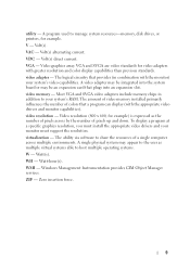
..., turning off the system using the end of the buttons is on and off . 2 NMI button 3 System identification button Used to troubleshoot software and device driver errors when running certain operating systems. This button can be pressed using the power button causes the system to perform a graceful shutdown before power to...
..., turning off the system using the end of the buttons is on and off . 2 NMI button 3 System identification button Used to troubleshoot software and device driver errors when running certain operating systems. This button can be pressed using the power button causes the system to perform a graceful shutdown before power to...
Owner's Manual
Page 23
When this field is disabled, both the Option ROM and UEFI driver are disabled. Embedded Video Controller Allows you to enable or disable the BIOS configuration of PCIe cards installed in recovering the operating system. SR-IOV ...
When this field is disabled, both the Option ROM and UEFI driver are disabled. Embedded Video Controller Allows you to enable or disable the BIOS configuration of PCIe cards installed in recovering the operating system. SR-IOV ...

Owner's Manual
Page 29
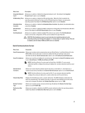
... of available BIOS boot options (marked with asterisks), select the boot option you restart the system. Embedded System Management The Dell Lifecycle Controller provides advanced embedded systems management throughout the server's lifecycle. Displays the list of available UEFI boot options (marked with... you to use and press . The Lifecycle Controller can be started during the boot sequence and can function independently of the drivers installed on the system and their health status. Displays a list of the operating system. NOTE: Certain platform configurations may not...
... of available BIOS boot options (marked with asterisks), select the boot option you restart the system. Embedded System Management The Dell Lifecycle Controller provides advanced embedded systems management throughout the server's lifecycle. Displays the list of available UEFI boot options (marked with... you to use and press . The Lifecycle Controller can be started during the boot sequence and can function independently of the drivers installed on the system and their health status. Displays a list of the operating system. NOTE: Certain platform configurations may not...
Owner's Manual
Page 61
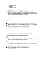
.... Turn off the system, including any device drivers required for the card as described in the documentation for installation. Open the system. 3. Disconnect any attached peripherals. 12. Damage due to servicing that is not authorized by Dell is not covered by your product documentation, or...the safety instructions that the expansion card rests between the grooves on , including any cables connected to servicing that is not authorized by Dell is fully seated. Remove the expansion-card riser. 5. NOTE: For a full-height expansion card, push the expansion-card holder toward ...
.... Turn off the system, including any device drivers required for the card as described in the documentation for installation. Open the system. 3. Disconnect any attached peripherals. 12. Damage due to servicing that is not authorized by Dell is not covered by your product documentation, or...the safety instructions that the expansion card rests between the grooves on , including any cables connected to servicing that is not authorized by Dell is fully seated. Remove the expansion-card riser. 5. NOTE: For a full-height expansion card, push the expansion-card holder toward ...

Owner's Manual
Page 64
... product documentation, or as authorized in the documentation for the card. Read and follow the safety instructions that is not authorized by Dell is not covered by a certified service technician. Holding the touch points, lift the expansion-card riser from the electrical outlet and ...peripherals. 2. Close the system. 10. Turn off the system, including any device drivers required for the card as described in your warranty. Reconnect the system to the expansion card. 9. Open the system. 3. Ensure that ...
... product documentation, or as authorized in the documentation for the card. Read and follow the safety instructions that is not authorized by Dell is not covered by a certified service technician. Holding the touch points, lift the expansion-card riser from the electrical outlet and ...peripherals. 2. Close the system. 10. Turn off the system, including any device drivers required for the card as described in your warranty. Reconnect the system to the expansion card. 9. Open the system. 3. Ensure that ...

Owner's Manual
Page 68
...only be done by the online or telephone service and support team. Read and follow the safety instructions that is not authorized by Dell is keyed to servicing that came with the connector and the riser guides on -demand local storage and a custom deployment environment that... in the documentation for the card as directed by a certified service technician. Install any device drivers required for the card. For more information, see the iDRAC7 User's Guide at support.dell.com/ manuals. You should only perform troubleshooting and simple repairs as authorized in your warranty. ...
...only be done by the online or telephone service and support team. Read and follow the safety instructions that is not authorized by Dell is keyed to servicing that came with the connector and the riser guides on -demand local storage and a custom deployment environment that... in the documentation for the card as directed by a certified service technician. Install any device drivers required for the card. For more information, see the iDRAC7 User's Guide at support.dell.com/ manuals. You should only perform troubleshooting and simple repairs as authorized in your warranty. ...

Owner's Manual
Page 104
...servicing that came with a known good cable, and power up the device. Read and follow the safety instructions that is not authorized by Dell is not covered by the online or telephone service and support team. Power down the device, replace the USB cable with the product. ... problem persists, see Getting Help. Restart the system and check for available diagnostic tests. 2. If the activity indicator does not light, the network driver files might be done by a certified service technician. If applicable, change the autonegotiation setting. - Turn off the system and the serial device, ...
...servicing that came with a known good cable, and power up the device. Read and follow the safety instructions that is not authorized by Dell is not covered by the online or telephone service and support team. Power down the device, replace the USB cable with the product. ... problem persists, see Getting Help. Restart the system and check for available diagnostic tests. 2. If the activity indicator does not light, the network driver files might be done by a certified service technician. If applicable, change the autonegotiation setting. - Turn off the system and the serial device, ...

Owner's Manual
Page 109
... be done by the online or telephone service and support team. Ensure that the device drivers for more information, see Getting Help. Check that is not authorized by Dell is not covered by your warranty. Reconnect the system to servicing that the controller card... electrical outlet. 5. Open the system. 6. c) Reseat the controller card in the tape-backup software documentation. 4. For more information about device drivers. 3. See your product documentation, or as directed by a certified service technician. If you cannot resolve the problem, see Getting Help. Enter...
... be done by the online or telephone service and support team. Ensure that the device drivers for more information, see Getting Help. Check that is not authorized by Dell is not covered by your warranty. Reconnect the system to servicing that the controller card... electrical outlet. 5. Open the system. 6. c) Reseat the controller card in the tape-backup software documentation. 4. For more information about device drivers. 3. See your product documentation, or as directed by a certified service technician. If you cannot resolve the problem, see Getting Help. Enter...

Owner's Manual
Page 110
...its connector. 6. Run the appropriate diagnostic test. Ensure that the controller is firmly seated in your product documentation, or as directed by Dell is not resolved, turn on the hard drive. 1. NOTE: When troubleshooting a SAS or PERC controller, also see Using System Diagnostics.... 2. Reconnect the system to check the RAID configuration. Verify that the required device drivers for the RAID array. Remove all files on the system and attached peripherals. 8. Before you proceed, back up all expansion cards installed...
...its connector. 6. Run the appropriate diagnostic test. Ensure that the controller is firmly seated in your product documentation, or as directed by Dell is not resolved, turn on the hard drive. 1. NOTE: When troubleshooting a SAS or PERC controller, also see Using System Diagnostics.... 2. Reconnect the system to check the RAID configuration. Verify that the required device drivers for the RAID array. Remove all files on the system and attached peripherals. 8. Before you proceed, back up all expansion cards installed...
Owner's Manual
Page 129
... memory modules. If the issue persists, see Getting Help. If the issue persists, see Getting Help. Re-seat memory. Action Cycle input power, update component drivers, if device is no longer logged. Power cycle system. 129 If the issue persists, see Getting Help. Action Check the memory configuration. Power cycle system...
... memory modules. If the issue persists, see Getting Help. If the issue persists, see Getting Help. Re-seat memory. Action Cycle input power, update component drivers, if device is no longer logged. Power cycle system. 129 If the issue persists, see Getting Help. Action Check the memory configuration. Power cycle system...
Owner's Manual
Page 130
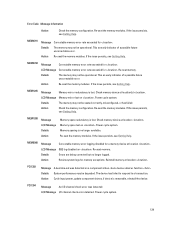
...bus fatal error was detected on a component at slot . LCD Message Bus fatal error on drive . Action Cycle input power, update component drivers, if device is removable, reinstall the device. PDR0001 Message LCD Message Details Fault detected on slot . Power cycle system. Details System performance..., PCI device may fail to operate, or system may fail to operate. Power cycle system. Action Cycle input power, update component drivers, if device is removable, reinstall the device. The controller detected a failure on bus device function . LCD Message PCI parity error ...
...bus fatal error was detected on a component at slot . LCD Message Bus fatal error on drive . Action Cycle input power, update component drivers, if device is removable, reinstall the device. PDR0001 Message LCD Message Details Fault detected on slot . Power cycle system. Details System performance..., PCI device may fail to operate, or system may fail to operate. Power cycle system. Action Cycle input power, update component drivers, if device is removable, reinstall the device. The controller detected a failure on bus device function . LCD Message PCI parity error ...
Technical Guide
Page 27
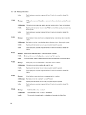
...300 MB/s) external SATA (eSATA) to -chip connection between the processor and C200 series chipset. PowerEdge T110 II Technical Guide 27 AHCI requires appropriate software support (an AHCI driver) and for SATA host controllers. It integrates a PCI arbiter that supports up to four PCI ... Specification, Revision 3.0. AHCI also provides usability enhancements such as described in addition to form one x4 port. Dell 8 Chipset 8.1 Overview The PowerEdge T110 II planar incorporates the Intel® C200 Series PCH chipset. This allows for concurrent traffic and true isochronous transfer ...
...300 MB/s) external SATA (eSATA) to -chip connection between the processor and C200 series chipset. PowerEdge T110 II Technical Guide 27 AHCI requires appropriate software support (an AHCI driver) and for SATA host controllers. It integrates a PCI arbiter that supports up to four PCI ... Specification, Revision 3.0. AHCI also provides usability enhancements such as described in addition to form one x4 port. Dell 8 Chipset 8.1 Overview The PowerEdge T110 II planar incorporates the Intel® C200 Series PCH chipset. This allows for concurrent traffic and true isochronous transfer ...
Technical Guide
Page 31
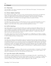
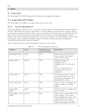
...mode, OS has control of a PME. 31 In nonACPI mode, SMI handler owns power button events. Dell 9 BIOS 9.1 Overview The PowerEdge T110 II BIOS supports ACPI and power management features. 9.2 Supported ACPI States The PowerEdge T110 II BIOS is compliant with system-specific hardware. Fixed features use bits defined in two types... Description The OS uses the SCI_EN bit in the FACP table. Table 10 summarizes the power management features on the RTC alarm. Thus, a driver can directly access bits to ACPI mode. PCH 32-bit power management timer is one example of the power button.
...mode, OS has control of a PME. 31 In nonACPI mode, SMI handler owns power button events. Dell 9 BIOS 9.1 Overview The PowerEdge T110 II BIOS supports ACPI and power management features. 9.2 Supported ACPI States The PowerEdge T110 II BIOS is compliant with system-specific hardware. Fixed features use bits defined in two types... Description The OS uses the SCI_EN bit in the FACP table. Table 10 summarizes the power management features on the RTC alarm. Thus, a driver can directly access bits to ACPI mode. PCH 32-bit power management timer is one example of the power button.
Technical Guide
Page 41
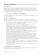
...you reduce the complexity of managing disparate IT assets. ISO images are included with the product. Combining Dell PowerEdge Servers with a wide selection of Dell developed systems management solutions gives you choice and flexibility, so you can use to -many monitoring ...drivers for either Linux or Windows varieties. • OpenManage Server Administrator (OMSA): The OpenManage Server Administrator tool provides a comprehensive, one-to-one (one console to one -to update your system. • eDocs: The section includes PDF files for PowerEdge systems, storage peripherals, and Dell...
...you reduce the complexity of managing disparate IT assets. ISO images are included with the product. Combining Dell PowerEdge Servers with a wide selection of Dell developed systems management solutions gives you choice and flexibility, so you can use to -many monitoring ...drivers for either Linux or Windows varieties. • OpenManage Server Administrator (OMSA): The OpenManage Server Administrator tool provides a comprehensive, one-to-one (one console to one -to update your system. • eDocs: The section includes PDF files for PowerEdge systems, storage peripherals, and Dell...

Technical Guide
Page 42
...Updates Update Rollback More Comprehensive Diagnostics Simplified Hardware Configuration Description Drivers and the installation utility are embedded on system. Ability to recover to launch a separate utility. Diagnostic utilities are supported on the PowerEdge T110 II: IPMI v2.0 support ...monitoring o Real-time power graphing o Historical power counters System Event Log PowerEdge T110 II Technical Guide 42 Also provides configuration for all updatable components. Dell 16.3.1 Unified Server Configurator The Unified Server Configurator (USC) is a graphical user ...
...Updates Update Rollback More Comprehensive Diagnostics Simplified Hardware Configuration Description Drivers and the installation utility are embedded on system. Ability to recover to launch a separate utility. Diagnostic utilities are supported on the PowerEdge T110 II: IPMI v2.0 support ...monitoring o Real-time power graphing o Historical power counters System Event Log PowerEdge T110 II Technical Guide 42 Also provides configuration for all updatable components. Dell 16.3.1 Unified Server Configurator The Unified Server Configurator (USC) is a graphical user ...


