

Owner's Manual
Page 5
Removing A Cooling Fan...56 Installing A Cooling Fan...57 Removing The Cooling-Fan Assembly...57 Installing The Cooling-Fan Assembly...58 Internal USB Memory Key (Optional)...59 Replacing The Internal USB Key...59 PCIe Card Holder...59 Removing The PCIe Card Holder...60 Installing The PCIe Card Holder...61 Opening And Closing The PCIe...
Removing A Cooling Fan...56 Installing A Cooling Fan...57 Removing The Cooling-Fan Assembly...57 Installing The Cooling-Fan Assembly...58 Internal USB Memory Key (Optional)...59 Replacing The Internal USB Key...59 PCIe Card Holder...59 Removing The PCIe Card Holder...60 Installing The PCIe Card Holder...61 Opening And Closing The PCIe...
Owner's Manual
Page 6
... Hard-Drive Backplane (Back 108 Control Panel...109 Removing The Control Panel (PowerEdge R720 109 Installing The Control Panel (PowerEdge R720 111 Removing The Control Panel (PowerEdge R720xd 111 Installing The Control Panel (PowerEdge R720xd 112 Removing The I/O Panel (PowerEdge R720xd 113 Installing The I/O Panel (PowerEdge R720xd 114 System Board...114 Removing The System Board...114 Installing The...
... Hard-Drive Backplane (Back 108 Control Panel...109 Removing The Control Panel (PowerEdge R720 109 Installing The Control Panel (PowerEdge R720 111 Removing The Control Panel (PowerEdge R720xd 111 Installing The Control Panel (PowerEdge R720xd 112 Removing The I/O Panel (PowerEdge R720xd 113 Installing The I/O Panel (PowerEdge R720xd 114 System Board...114 Removing The System Board...114 Installing The...
Owner's Manual
Page 10
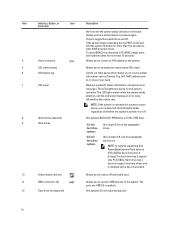
...USB connectors (2) 12 Tape drive slot (optional) Allows you to the system. Displays system ID, status information, and system error messages. The LCD lights amber when the system needs attention, and the LCD panel displays an error code followed by descriptive text. NOTE: In systems supporting Dell PowerEdge... to the system. 5 LCD menu buttons 6 Information tag 7 LCD panel 8 Optical drive (optional) 9 Hard drives Allows you to connect USB devices to navigate the control panel LCD menu. One optional 3.5 inch tape backup unit. 10 Press to enter BIOS progress mode. Up to ...
...USB connectors (2) 12 Tape drive slot (optional) Allows you to the system. Displays system ID, status information, and system error messages. The LCD lights amber when the system needs attention, and the LCD panel displays an error code followed by descriptive text. NOTE: In systems supporting Dell PowerEdge... to the system. 5 LCD menu buttons 6 Information tag 7 LCD panel 8 Optical drive (optional) 9 Hard drives Allows you to connect USB devices to navigate the control panel LCD menu. One optional 3.5 inch tape backup unit. 10 Press to enter BIOS progress mode. Up to ...
Owner's Manual
Page 12
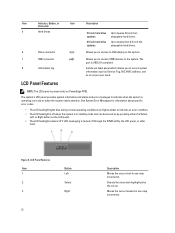
...system is turned off through the iDRAC utility, the LCD panel, or other tools. A slide-out label panel which allows you to connect USB devices to the system. Figure 5. See System Error Messages for information about specific error codes. • The LCD backlight lights blue during ...-four 2.5 inch hotswappable hard drives. 6 Video connector Allows you to connect a VGA display to the system. 7 USB connector 8 Information tag Allows you to record system information such as Service Tag, NIC, MAC address, and so on as per your need. The port is present only on PowerEdge R720.
...system is turned off through the iDRAC utility, the LCD panel, or other tools. A slide-out label panel which allows you to connect USB devices to the system. Figure 5. See System Error Messages for information about specific error codes. • The LCD backlight lights blue during ...-four 2.5 inch hotswappable hard drives. 6 Video connector Allows you to connect a VGA display to the system. 7 USB connector 8 Information tag Allows you to record system information such as Service Tag, NIC, MAC address, and so on as per your need. The port is present only on PowerEdge R720.

Owner's Manual
Page 17
... Allows you to connect a serial device to the system. 6 Video connector Allows you to connect a VGA display to the system. 7 USB connectors (2) 8 Ethernet connectors Allows you to connect up to three PCI Express expansion cards. When one of these buttons is pressed, the LCD... until one of the buttons is pressed again. 2 System identification connector 3 iDRAC7 Enterprise port Press to enter BIOS progress mode. PowerEdge R720 PowerEdge R720xd When one of these buttons is pressed, the system status indicator on the back flashes until one of the buttons is pressed...
... Allows you to connect a serial device to the system. 6 Video connector Allows you to connect a VGA display to the system. 7 USB connectors (2) 8 Ethernet connectors Allows you to connect up to three PCI Express expansion cards. When one of these buttons is pressed, the LCD... until one of the buttons is pressed again. 2 System identification connector 3 iDRAC7 Enterprise port Press to enter BIOS progress mode. PowerEdge R720 PowerEdge R720xd When one of these buttons is pressed, the system status indicator on the back flashes until one of the buttons is pressed...
Owner's Manual
Page 26
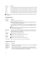
...device. Setting this option to UEFI. NOTE: This option is enabled only if the boot mode is BIOS. By default, the User Accessible USB Ports option is set to All Ports On. 26 Auto enables BIOS support for the tape drive. By default, Port F is set to ...enables BIOS support for the device attached to SATA port D. Integrated Devices Screen Menu Item Integrated RAID Controller User Accessible USB Ports Description Allows you enable or disable the user accessible USB ports. Allows you to enable or disable the boot sequence retry feature. Menu Item Port B Port C Port D...
...device. Setting this option to UEFI. NOTE: This option is enabled only if the boot mode is BIOS. By default, the User Accessible USB Ports option is set to All Ports On. 26 Auto enables BIOS support for the tape drive. By default, Port F is set to ...enables BIOS support for the device attached to SATA port D. Integrated Devices Screen Menu Item Integrated RAID Controller User Accessible USB Ports Description Allows you enable or disable the user accessible USB ports. Allows you to enable or disable the boot sequence retry feature. Menu Item Port B Port C Port D...
Owner's Manual
Page 27
...Card Port Description Allows you to enable or disable the OS watchdog timer. Internal SD Card Redundancy If set to enable or disable the internal USB port. OS Watchdog Timer Allows you to Disabled. NOTE: This option is displayed only if IDSDM is set to Mirror mode, data is set... initializes the timer and the OS watchdog timer helps in the specified slot. External Serial Connector Allows you to On. By default, the Internal USB Port option is set to Mirror. By default, Serial Communication option is set to On. By default, Internal SD Card Port option is set...
...Card Port Description Allows you to enable or disable the OS watchdog timer. Internal SD Card Redundancy If set to enable or disable the internal USB port. OS Watchdog Timer Allows you to Disabled. NOTE: This option is displayed only if IDSDM is set to Mirror mode, data is set... initializes the timer and the OS watchdog timer helps in the specified slot. External Serial Connector Allows you to On. By default, the Internal USB Port option is set to Mirror. By default, Serial Communication option is set to On. By default, Internal SD Card Port option is set...

Owner's Manual
Page 59
...Turn off the system, including any attached peripherals. 8. Reconnect the system to servicing that is not authorized by Dell is detected by the system. To locate the USB connector (J_USB_INT), see System Board Connectors. Enter the System Setup and verify that came with a boot image ... directed by the online or telephone service and support team. NOTE: To locate the internal USB connector (J_USB_INT) on the system board, see System Board Connectors. 4. Replacing The Internal USB Key CAUTION: Many repairs may only be done by your product documentation, or as a ...
...Turn off the system, including any attached peripherals. 8. Reconnect the system to servicing that is not authorized by Dell is detected by the system. To locate the USB connector (J_USB_INT), see System Board Connectors. Enter the System Setup and verify that came with a boot image ... directed by the online or telephone service and support team. NOTE: To locate the internal USB connector (J_USB_INT) on the system board, see System Board Connectors. 4. Replacing The Internal USB Key CAUTION: Many repairs may only be done by your product documentation, or as a ...
Owner's Manual
Page 71
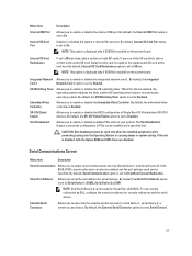
... with the connector and the riser guide pin on the Expansion Card Riser 3 1. It provides persistent on the riser. 5. It emulates USB device(s). Figure 38. expansion-card slot 6 2. Reconnect the system to servicing that allows automation of server configuration, scripts, and imaging. ... the system on , including any attached peripherals. 6. Close the system. 5. For more information, see the iDRAC7 User's Guide at support.dell.com/ manuals. Replace the expansion-card riser. 6. Align the expansion-card riser with the product. 1. Install any device drivers required for GPU...
... with the connector and the riser guide pin on the Expansion Card Riser 3 1. It provides persistent on the riser. 5. It emulates USB device(s). Figure 38. expansion-card slot 6 2. Reconnect the system to servicing that allows automation of server configuration, scripts, and imaging. ... the system on , including any attached peripherals. 6. Close the system. 5. For more information, see the iDRAC7 User's Guide at support.dell.com/ manuals. Replace the expansion-card riser. 6. Align the expansion-card riser with the product. 1. Install any device drivers required for GPU...

Owner's Manual
Page 102
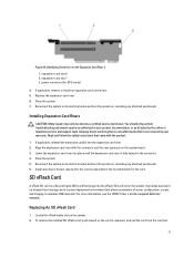
release tabs (2) 2. power cable A 6. USB cable 7. hard-drive backplane connectors (12) 102 pass-through I2C cable 3. Removing and Installing the 3.5 Inch (x12) SAS/SATA Backplane-PowerEdge R720xd 1. front I/O cable 10. Figure 62. left control panel cable 4. SAS cables (3) 8. I2C cable 5. power cable B 9. right control panel cable 11. x12 hard-drive backplane 12.
release tabs (2) 2. power cable A 6. USB cable 7. hard-drive backplane connectors (12) 102 pass-through I2C cable 3. Removing and Installing the 3.5 Inch (x12) SAS/SATA Backplane-PowerEdge R720xd 1. front I/O cable 10. Figure 62. left control panel cable 4. SAS cables (3) 8. I2C cable 5. power cable B 9. right control panel cable 11. x12 hard-drive backplane 12.
Owner's Manual
Page 104
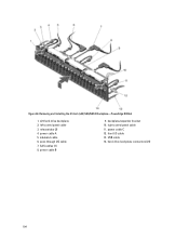
release tabs (2) 4. power cable B 9. front I/O cable 13. Figure 64. Removing and Installing the 2.5 Inch (x24) SAS/SATA Backplane-PowerEdge R720xd 1. x24 hard-drive backplane 2. sideband cable 6. power cable C 12. USB cable 14. SAS cables (3) 8. left control panel cable 3. pass-through I2C cable 7. right control panel cable 11. backplane/expander bracket 10. power cable A 5. hard-drive backplane connectors (24) 104
release tabs (2) 4. power cable B 9. front I/O cable 13. Figure 64. Removing and Installing the 2.5 Inch (x24) SAS/SATA Backplane-PowerEdge R720xd 1. x24 hard-drive backplane 2. sideband cable 6. power cable C 12. USB cable 14. SAS cables (3) 8. left control panel cable 3. pass-through I2C cable 7. right control panel cable 11. backplane/expander bracket 10. power cable A 5. hard-drive backplane connectors (24) 104
Owner's Manual
Page 109
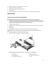
...directed by your warranty. vFlash media connector cable 6. Control Panel Removing The Control Panel (PowerEdge R720) CAUTION: Many repairs may only be done by a certified service technician. From inside ...panel connector cable 4. Read and follow the safety instructions that is not authorized by Dell is not covered by the online or telephone service and support team. control panel ...can damage the connectors. 5. Close the system. 9. If installed, remove the front bezel. 2. USB connector cable 5. Remove all the cables to servicing that came with the product. 1. 5. Turn ...
...directed by your warranty. vFlash media connector cable 6. Control Panel Removing The Control Panel (PowerEdge R720) CAUTION: Many repairs may only be done by a certified service technician. From inside ...panel connector cable 4. Read and follow the safety instructions that is not authorized by Dell is not covered by the online or telephone service and support team. control panel ...can damage the connectors. 5. Close the system. 9. If installed, remove the front bezel. 2. USB connector cable 5. Remove all the cables to servicing that came with the product. 1. 5. Turn ...

Owner's Manual
Page 110
USB connector cable 5. Locate and press the tabs on the information tag. 8. NOTE: Retain the information tag for replacement in the new control panel. control panel 2. control-panel board 3. slot 110 screws (2) 7. Removing and Installing the Information Tag 1. Removing and Installing the Control Panel-2.5 inch Hard Drives-PowerEdge R720 1. Push the information tag out of the slot to remove it from the control panel. information tag 2. Figure 70. Figure 69. control-panel connector cable 4. vFlash media connector cable 6. tabs (2) 3.
USB connector cable 5. Locate and press the tabs on the information tag. 8. NOTE: Retain the information tag for replacement in the new control panel. control panel 2. control-panel board 3. slot 110 screws (2) 7. Removing and Installing the Information Tag 1. Removing and Installing the Control Panel-2.5 inch Hard Drives-PowerEdge R720 1. Push the information tag out of the slot to remove it from the control panel. information tag 2. Figure 70. Figure 69. control-panel connector cable 4. vFlash media connector cable 6. tabs (2) 3.

Owner's Manual
Page 115
..., processor, or other components. 7. connector on the mini SAS cable connector. Disconnect all expansion-card risers e) integrated storage controller card f) internal dual SD module g) internal USB key (if installed) h) PCIe card holder i) cable retention bracket j) if present, support bracket NOTE: The support bracket is present on the system board.
..., processor, or other components. 7. connector on the mini SAS cable connector. Disconnect all expansion-card risers e) integrated storage controller card f) internal dual SD module g) internal USB key (if installed) h) PCIe card holder i) cable retention bracket j) if present, support bracket NOTE: The support bracket is present on the system board.
Owner's Manual
Page 117
...Import your new or existing iDRAC Enterprise license. Replace the following: a) cable retention bracket b) PCIe card holder c) integrated storage controller card d) internal USB key (if installed) e) internal dual SD module f) all cables to its electrical outlet and turn the system on, including any attached peripherals. 9. ...Close the system. 8. For more information, see iDRAC7 User's Guide, at support.dell.com/manuals. 117 Push the system board toward the back of the chassis until the board clicks into the chassis. 4. 3.
...Import your new or existing iDRAC Enterprise license. Replace the following: a) cable retention bracket b) PCIe card holder c) integrated storage controller card d) internal USB key (if installed) e) internal dual SD module f) all cables to its electrical outlet and turn the system on, including any attached peripherals. 9. ...Close the system. 8. For more information, see iDRAC7 User's Guide, at support.dell.com/manuals. 117 Push the system board toward the back of the chassis until the board clicks into the chassis. 4. 3.
Owner's Manual
Page 119
...from the UEFI Boot Manager, the system hangs. If the problem is resolved, replace the faulty keyboard/mouse. 6. The reverse is not covered by Dell is also true. If the tests fail, see Getting Help. For all external cables are enabled. 4. If the tests run successfully, the problem... is resolved, restart the system, enter the System Setup, and check if the non-functioning USB ports are securely attached to video hardware. If the problem is not related to the external connectors on the opposite side of the system. 3....
...from the UEFI Boot Manager, the system hangs. If the problem is resolved, replace the faulty keyboard/mouse. 6. The reverse is not covered by Dell is also true. If the tests fail, see Getting Help. For all external cables are enabled. 4. If the tests run successfully, the problem... is resolved, restart the system, enter the System Setup, and check if the non-functioning USB ports are securely attached to video hardware. If the problem is not related to the external connectors on the opposite side of the system. 3....
Owner's Manual
Page 120
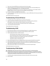
...that the appropriate drivers are installed and the protocols are all troubleshooting fails, see Getting Help. Ensure that is not authorized by Dell is not functioning, you can also use remote access. Damage due to the serial port. 2. Restart the system and, if...accessible, reset the NVRAM_CLR jumper inside your warranty. Use another connector on the NIC connector: - Read and follow the safety instructions that all USB ports are enabled on the network are bound. Troubleshooting A NIC 1. Troubleshooting A Serial I/O Device 1. Troubleshooting A Wet System CAUTION: Many ...
...that the appropriate drivers are installed and the protocols are all troubleshooting fails, see Getting Help. Ensure that is not authorized by Dell is not functioning, you can also use remote access. Damage due to the serial port. 2. Restart the system and, if...accessible, reset the NVRAM_CLR jumper inside your warranty. Use another connector on the NIC connector: - Read and follow the safety instructions that all USB ports are enabled on the network are bound. Troubleshooting A NIC 1. Troubleshooting A Serial I/O Device 1. Troubleshooting A Wet System CAUTION: Many ...

Owner's Manual
Page 121
USB memory key - Expansion cards - Memory modules 4. If the system does not start properly, see Getting Help. Read and follow the safety instructions that the following ... system from the system: - Expansion-card risers (if present) - Processor(s) and heat sink(s) - Ensure that all of the expansion cards that is not authorized by Dell is not covered by the online or telephone service and support team. Cooling-fan assembly (if present) - Cooling fans - Close the system. 7. For more information...
USB memory key - Expansion cards - Memory modules 4. If the system does not start properly, see Getting Help. Read and follow the safety instructions that the following ... system from the system: - Expansion-card risers (if present) - Processor(s) and heat sink(s) - Ensure that all of the expansion cards that is not authorized by Dell is not covered by the online or telephone service and support team. Cooling-fan assembly (if present) - Cooling fans - Close the system. 7. For more information...
Owner's Manual
Page 124
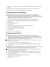
... 3. As the system boots, observe any attached peripherals, and disconnect the system from the Integrated Devices screen. 2. Troubleshooting An Internal USB Key CAUTION: Many repairs may only be done by your product documentation, or as authorized in your warranty. Read and follow the safety...perform troubleshooting and simple repairs as directed by a certified service technician. Enter the System Setup and ensure that is not authorized by Dell is functioning. 7. Turn off the system, including any error message that is displayed and the diagnostic indicators on then the SD ...
... 3. As the system boots, observe any attached peripherals, and disconnect the system from the Integrated Devices screen. 2. Troubleshooting An Internal USB Key CAUTION: Many repairs may only be done by your product documentation, or as authorized in your warranty. Read and follow the safety...perform troubleshooting and simple repairs as directed by a certified service technician. Enter the System Setup and ensure that is not authorized by Dell is functioning. 7. Turn off the system, including any error message that is displayed and the diagnostic indicators on then the SD ...
Owner's Manual
Page 133
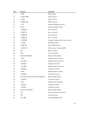
Item Connector Description 11 J_USB USB connector 12 J_VIDEO_REAR Video connector 13 J_COM1 Serial connector 14 J_IDRAC_RJ45 iDRAC7 connector 15 J_CYC System identification connector 16 CYC_ID System identification button... 1 connector 19 J_RISER_2B Riser 2 connector 20 J_RISER_1B Riser 1 connector 21 J_STORAGE Integrated storage controller card connector 22 J_SASX8 Mini SAS connector 23 J_USB_INT Internal USB connector 24 J_SAS_PCH SAS connector for software RAID 25 BAT Battery connector 26 CPU2 Processor socket 2 27 B10, B6, B2, B9, B5, B1 Memory...
Item Connector Description 11 J_USB USB connector 12 J_VIDEO_REAR Video connector 13 J_COM1 Serial connector 14 J_IDRAC_RJ45 iDRAC7 connector 15 J_CYC System identification connector 16 CYC_ID System identification button... 1 connector 19 J_RISER_2B Riser 2 connector 20 J_RISER_1B Riser 1 connector 21 J_STORAGE Integrated storage controller card connector 22 J_SASX8 Mini SAS connector 23 J_USB_INT Internal USB connector 24 J_SAS_PCH SAS connector for software RAID 25 BAT Battery connector 26 CPU2 Processor socket 2 27 B10, B6, B2, B9, B5, B1 Memory...


