
Owner's Manual
Page 4
...The Boot Manager Navigation Keys...31 Boot Manager Screen...31 UEFI Boot Menu...32 Embedded System Management...32 iDRAC Settings Utility...32 Entering The iDRAC Settings Utility...32 3 Installing System Components 33 Recommended Tools...33 Front Bezel (Optional)...33 Installing The ...Specific Guidelines...41 Advanced ECC (Lockstep)...41 Memory Optimized (Independent Channel) Mode 42 Memory Sparing...42 Memory Mirroring...42 Sample Memory Configurations...42 Removing Memory Modules...44 Installing Memory Modules...45 Hard Drives...45 Removing A 3.5 Inch Hard-Drive Blank...46 Installing A 3.5...
...The Boot Manager Navigation Keys...31 Boot Manager Screen...31 UEFI Boot Menu...32 Embedded System Management...32 iDRAC Settings Utility...32 Entering The iDRAC Settings Utility...32 3 Installing System Components 33 Recommended Tools...33 Front Bezel (Optional)...33 Installing The ...Specific Guidelines...41 Advanced ECC (Lockstep)...41 Memory Optimized (Independent Channel) Mode 42 Memory Sparing...42 Memory Mirroring...42 Sample Memory Configurations...42 Removing Memory Modules...44 Installing Memory Modules...45 Hard Drives...45 Removing A 3.5 Inch Hard-Drive Blank...46 Installing A 3.5...
Owner's Manual
Page 11
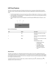
... view the Home screen. To navigate to the Home screen from another menu, continue to repeat the cycle Home Screen The Home screen displays user-configurable information about specific error codes. • The LCD backlight lights blue during normal system operation when there are no status messages or errors. This screen... increments. LCD Panel Features The system's LCD panel provides system information and status and error messages to indicate when the system is off through the iDRAC utility, the LCD panel, or other tools. Figure 3.
... view the Home screen. To navigate to the Home screen from another menu, continue to repeat the cycle Home Screen The Home screen displays user-configurable information about specific error codes. • The LCD backlight lights blue during normal system operation when there are no status messages or errors. This screen... increments. LCD Panel Features The system's LCD panel provides system information and status and error messages to indicate when the system is off through the iDRAC utility, the LCD panel, or other tools. Figure 3.
Owner's Manual
Page 12
...power output of the system in the Set home submenu of the system in the SEL. Select Setup DNS to enable DNS and to be configured in BTU/hr or Watts. This is selected, the available fields are available. Addresses include DNS (Primary and Secondary), Gateway, IP, and...a format that can be set as the default on the LCD Home screen. Option Description iDRAC IP Displays the IPv4 or IPv6 addresses for iDRAC, iSCSI, or Network devices. The display format can be configured in a simplified user-friendly description. Temperature Displays the temperature of the Setup menu. 12 ...
...power output of the system in the Set home submenu of the system in the SEL. Select Setup DNS to enable DNS and to be configured in BTU/hr or Watts. This is selected, the available fields are available. Addresses include DNS (Primary and Secondary), Gateway, IP, and...a format that can be set as the default on the LCD Home screen. Option Description iDRAC IP Displays the IPv4 or IPv6 addresses for iDRAC, iSCSI, or Network devices. The display format can be configured in a simplified user-friendly description. Temperature Displays the temperature of the Setup menu. 12 ...
Owner's Manual
Page 19
... enhanced 64-bit boot interface based on the system's boot configuration. The Dell LC2 supports systems management features such as operating system deployment, hardware diagnostics, platform updates, and platform configuration, using the: • Standard graphical browser, which is ...iDRAC license purchased. Enters System Services, which is determined by default • Text browser, which opens the Dell Lifecycle Controller 2 (LC2). From the System Setup, you can: • Change the NVRAM settings after you add or remove hardware • View the system hardware configuration...
... enhanced 64-bit boot interface based on the system's boot configuration. The Dell LC2 supports systems management features such as operating system deployment, hardware diagnostics, platform updates, and platform configuration, using the: • Standard graphical browser, which is ...iDRAC license purchased. Enters System Services, which is determined by default • Text browser, which opens the Dell Lifecycle Controller 2 (LC2). From the System Setup, you can: • Change the NVRAM settings after you add or remove hardware • View the system hardware configuration...
Owner's Manual
Page 21
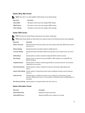
...ports and specify related features and options. Miscellaneous Settings Displays options to view and configure BIOS settings. Displays the BIOS version installed on . Menu Item System BIOS iDRAC Settings Device Settings Description This option is used to change the processor power management... settings, memory frequency, and so on the system. 21 System Profile Settings Displays options to view and configure iDRAC settings. This option is used to their respective options in the following sections, where applicable. Enables you to specify related...
...ports and specify related features and options. Miscellaneous Settings Displays options to view and configure BIOS settings. Displays the BIOS version installed on . Menu Item System BIOS iDRAC Settings Device Settings Description This option is used to change the processor power management... settings, memory frequency, and so on the system. 21 System Profile Settings Displays options to view and configure iDRAC settings. This option is used to their respective options in the following sections, where applicable. Enables you to specify related...
Owner's Manual
Page 32
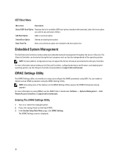
... during the boot sequence and can enable or disable various iDRAC parameters using the iDRAC Settings Utility. NOTE: Certain platform configurations may not support the full set of the features on using iDRAC, see the Lifecycle Controller documentation at support.dell.com/manuals. Entering The iDRAC Settings Utility 1. In the System Setup Main Menu page, click...
... during the boot sequence and can enable or disable various iDRAC parameters using the iDRAC Settings Utility. NOTE: Certain platform configurations may not support the full set of the features on using iDRAC, see the Lifecycle Controller documentation at support.dell.com/manuals. Entering The iDRAC Settings Utility 1. In the System Setup Main Menu page, click...
Owner's Manual
Page 57
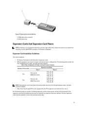
...fit. Replacing the Internal USB Key 1. USB memory key connector 2. Use the following table provides the riser configurations for the PCIe expansion card slot (slot 2) on and no BIOS POST message or F1/F2 pause is supported for single- ...using the slot priority indicated. Figure 27. and dual-processor configurations. and Dual-Processor Systems Number of Processors Expansion Card Slots Riser 1 Riser 2 One PCIE_G2_X4 iDRAC Ports Card PCIE_G3_X8 PCIE_G3_X4 PCIE_G3_X4 Two PCIE_G3_X16 iDRAC Ports Card PCIE_G3_X8 PCIE_G3_X8 PCIE_G3_X8 NOTE: The expansion-card risers ...
...fit. Replacing the Internal USB Key 1. USB memory key connector 2. Use the following table provides the riser configurations for the PCIe expansion card slot (slot 2) on and no BIOS POST message or F1/F2 pause is supported for single- ...using the slot priority indicated. Figure 27. and dual-processor configurations. and Dual-Processor Systems Number of Processors Expansion Card Slots Riser 1 Riser 2 One PCIE_G2_X4 iDRAC Ports Card PCIE_G3_X8 PCIE_G3_X4 PCIE_G3_X4 Two PCIE_G3_X16 iDRAC Ports Card PCIE_G3_X8 PCIE_G3_X8 PCIE_G3_X8 NOTE: The expansion-card risers ...
Owner's Manual
Page 65
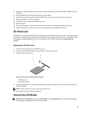
...system. It emulates USB device(s). For more information, see the iDRAC7 User's Guide at support.dell.com/ manuals. Removing and Installing the SD vFlash Card 1. Press inward on -demand local ...Mode in the documentation for the card as described in the Integrated Devices screen of server configuration, scripts, and imaging. Holding the card by its electrical outlet and turn the system ...slot is replicated from the card slot. If applicable, connect cables to another. 65 Align the iDRAC Ports card bracket with the hooks on , including any device drivers required for the card. ...
...system. It emulates USB device(s). For more information, see the iDRAC7 User's Guide at support.dell.com/ manuals. Removing and Installing the SD vFlash Card 1. Press inward on -demand local ...Mode in the documentation for the card as described in the Integrated Devices screen of server configuration, scripts, and imaging. Holding the card by its electrical outlet and turn the system ...slot is replicated from the card slot. If applicable, connect cables to another. 65 Align the iDRAC Ports card bracket with the hooks on , including any device drivers required for the card. ...

Owner's Manual
Page 111
The configuration settings are retained at the next system boot (pins 1-3). 111 The password feature is enabled (pins 2-4). NVRAM_CLR (default) The configuration settings are cleared at system boot (pins 3-5). System Board Jumper Settings Jumper Setting Description PWRD_EN (default) The password feature is disabled (pins 4-6). iDRAC local access is unlocked at the next AC power cycle. 6 Jumpers And Connectors System Board Jumper Settings For information on resetting the password jumper to disable a password, see Disabling A Forgotten Password. Table 5.
The configuration settings are retained at the next system boot (pins 1-3). 111 The password feature is enabled (pins 2-4). NVRAM_CLR (default) The configuration settings are cleared at system boot (pins 3-5). System Board Jumper Settings Jumper Setting Description PWRD_EN (default) The password feature is disabled (pins 4-6). iDRAC local access is unlocked at the next AC power cycle. 6 Jumpers And Connectors System Board Jumper Settings For information on resetting the password jumper to disable a password, see Disabling A Forgotten Password. Table 5.
Owner's Manual
Page 131
...The chassis is on Internal Dual SD Module . Check chassis cover. SEL0006 Message Details Action All event logging is installed but improperly configured or failed to initialize. If unintended, re-enable logging. SEL0008 Message Log is full, additional events are not captured. Details When ...SD module. Internal Dual SD Module failed. Action Close the chassis and verify hardware inventory. Action Reboot the management controller or iDRAC. SEC0033 Message The chassis is open while the power is displayed when all event logging has been disabled by the user. LCD...
...The chassis is on Internal Dual SD Module . Check chassis cover. SEL0006 Message Details Action All event logging is installed but improperly configured or failed to initialize. If unintended, re-enable logging. SEL0008 Message Log is full, additional events are not captured. Details When ...SD module. Internal Dual SD Module failed. Action Close the chassis and verify hardware inventory. Action Reboot the management controller or iDRAC. SEC0033 Message The chassis is open while the power is displayed when all event logging has been disabled by the user. LCD...


