
Glossary
Page 1
... a hard drive. C - CIM - Alternating current. A standard interface for security or tracking purposes. The modules are mounted into a chassis that allows the processor to start your system's hard drive(s) on the dictionary. British thermal unit. Your system contains an expansion bus that...system if the system will not boot from SNMP agents. An information pathway between the processor and RAM. CA - Centimeter(s). 1 Dell™ Glossary NOTE: For additional information on storage terminology, visit the Storage Networking Industry Association's website at www.snia.org and click...
... a hard drive. C - CIM - Alternating current. A standard interface for security or tracking purposes. The modules are mounted into a chassis that allows the processor to start your system's hard drive(s) on the dictionary. British thermal unit. Your system contains an expansion bus that...system if the system will not boot from SNMP agents. An information pathway between the processor and RAM. CA - Centimeter(s). 1 Dell™ Glossary NOTE: For additional information on storage terminology, visit the Storage Networking Industry Association's website at www.snia.org and click...
Owner's Manual
Page 14
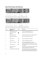
... the system. Connects the optional system status indicator assembly through the optional cable management arm. Back-Panel Features and Indicators-Non-Redundant Power Supply Unit Chassis Item Indicator, Button, or Icon Description Connector 1 PCIe expansion card slot 1 Connects a PCI Express expansion card. 2 vFlash media card slot (Optional) Allows you to insert... SFP+ connector Connect USB devices to locate a particular system within a rack. The ports are USB 2.0-compliant. Back-Panel Features and Indicators-Redundant Power Supply Unit Chassis Figure 6.
... the system. Connects the optional system status indicator assembly through the optional cable management arm. Back-Panel Features and Indicators-Non-Redundant Power Supply Unit Chassis Item Indicator, Button, or Icon Description Connector 1 PCIe expansion card slot 1 Connects a PCI Express expansion card. 2 vFlash media card slot (Optional) Allows you to insert... SFP+ connector Connect USB devices to locate a particular system within a rack. The ports are USB 2.0-compliant. Back-Panel Features and Indicators-Redundant Power Supply Unit Chassis Figure 6.
Owner's Manual
Page 33
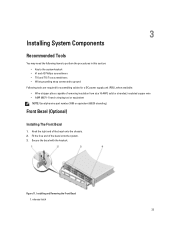
... supply unit (PSU), when available: • Wire-stripper pliers capable of the bezel onto the system. 3. Hook the right end of the bezel onto the chassis. 2.
... supply unit (PSU), when available: • Wire-stripper pliers capable of the bezel onto the system. 3. Hook the right end of the bezel onto the chassis. 2.

Owner's Manual
Page 35
... attached peripherals. Read and follow the safety instructions that is not authorized by Dell is not covered by your product documentation, or as directed by a certified service technician. Lift the latch on the chassis. 3. Reconnect the system to secure the cover. 5. NOTE: Components that ...it clears the chassis hooks and lays flush on the cover. 2. Figure 12. latch 3. system cover 2. Damage ...
... attached peripherals. Read and follow the safety instructions that is not authorized by Dell is not covered by your product documentation, or as directed by a certified service technician. Lift the latch on the chassis. 3. Reconnect the system to secure the cover. 5. NOTE: Components that ...it clears the chassis hooks and lays flush on the cover. 2. Figure 12. latch 3. system cover 2. Damage ...
Owner's Manual
Page 36
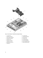
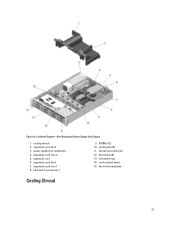
expansion card 6. expansion-card riser 1 8. DIMMs (12) 10. power-distribution board 17. cooling shroud 2. information tag 14. hard-drive backplane 16. Figure 13. heat sink for processor 1 9. cooling fans (6) 11. hard drives (8) 13. expansion-card riser 2 5. control-panel board 15. power-interposer board 36 Inside the System-Redundant Power Supply Unit Chassis 1. power supply (redundant) 4. expansion-card latch 7. optical drive (optional) 12. expansion-card latch 3.
expansion card 6. expansion-card riser 1 8. DIMMs (12) 10. power-distribution board 17. cooling shroud 2. information tag 14. hard-drive backplane 16. Figure 13. heat sink for processor 1 9. cooling fans (6) 11. hard drives (8) 13. expansion-card riser 2 5. control-panel board 15. power-interposer board 36 Inside the System-Redundant Power Supply Unit Chassis 1. power supply (redundant) 4. expansion-card latch 7. optical drive (optional) 12. expansion-card latch 3.
Owner's Manual
Page 37
Figure 14. power supply (non-redundant) 4. heat sink for processor 1 9. expansion-card riser 2 5. cooling fans (6) 11. optical drive (optional) 12. hard-drive backplane Cooling Shroud 37 Inside the System-Non-Redundant Power Supply Unit Chassis 1. expansion-card latch 3. expansion card 6. expansion-card latch 7. expansion-card riser 1 8. hard drives (8) 13. information tag 14. cooling shroud 2. control-panel board 15. DIMMs (12) 10.
Figure 14. power supply (non-redundant) 4. heat sink for processor 1 9. expansion-card riser 2 5. cooling fans (6) 11. optical drive (optional) 12. hard-drive backplane Cooling Shroud 37 Inside the System-Non-Redundant Power Supply Unit Chassis 1. expansion-card latch 3. expansion card 6. expansion-card latch 7. expansion-card riser 1 8. hard drives (8) 13. information tag 14. cooling shroud 2. control-panel board 15. DIMMs (12) 10.
Owner's Manual
Page 39
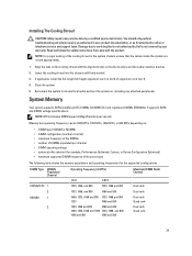
... retention bracket. 2. Align the tabs on the cooling shroud with the product. Lower the cooling shroud into the chassis until firmly seated. 3. Reconnect the system to servicing that is not authorized by Dell is not covered by your product documentation, or as authorized in your warranty. System Memory Your system supports DDR3...
... retention bracket. 2. Align the tabs on the cooling shroud with the product. Lower the cooling shroud into the chassis until firmly seated. 3. Reconnect the system to servicing that is not authorized by Dell is not covered by your product documentation, or as authorized in your warranty. System Memory Your system supports DDR3...

Owner's Manual
Page 47
... hard-drive slots must have hard-drive blanks installed. Using a screwdriver, push the release tabs to unlock the dual slot hard-drive blank from the chassis. 3. 3.
... hard-drive slots must have hard-drive blanks installed. Using a screwdriver, push the release tabs to unlock the dual slot hard-drive blank from the chassis. 3. 3.
Owner's Manual
Page 54
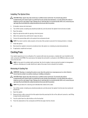
...system supports up to its electrical outlet and turn the system on, including any attached peripherals. 9. Remove the fan cable connector from the chassis. 54 Installing The Optical Drive CAUTION: Many repairs may only be done by a certified service technician. You should only perform troubleshooting and... the proper fan by the online or telephone service and support team. Read and follow the safety instructions that is not authorized by Dell is referenced by a certified service technician. Damage due to the optical drive and system board. Turn off the system, including any ...
...system supports up to its electrical outlet and turn the system on, including any attached peripherals. 9. Remove the fan cable connector from the chassis. 54 Installing The Optical Drive CAUTION: Many repairs may only be done by a certified service technician. You should only perform troubleshooting and... the proper fan by the online or telephone service and support team. Read and follow the safety instructions that is not authorized by Dell is referenced by a certified service technician. Damage due to the optical drive and system board. Turn off the system, including any ...
Owner's Manual
Page 65
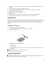
...(SD) card that the card-edge connector aligns with the iDRAC Ports card connector. 7. For more information, see the iDRAC7 User's Guide at support.dell.com/ manuals. To install the SD vFlash card, with the hooks on the iDRAC Ports card. 2. Holding the card by its electrical outlet and ... on the card to the iDRAC Ports card. 11. It provides persistent on the card to another. 65 Locate the vFlash media slot on the chassis. 8. Removing and Installing the SD vFlash Card 1. Internal Dual SD Module NOTE: When the Redundancy option is replicated from the card slot. Reconnect ...
...(SD) card that the card-edge connector aligns with the iDRAC Ports card connector. 7. For more information, see the iDRAC7 User's Guide at support.dell.com/ manuals. To install the SD vFlash card, with the hooks on the iDRAC Ports card. 2. Holding the card by its electrical outlet and ... on the card to the iDRAC Ports card. 11. It provides persistent on the card to another. 65 Locate the vFlash media slot on the chassis. 8. Removing and Installing the SD vFlash Card 1. Internal Dual SD Module NOTE: When the Redundancy option is replicated from the card slot. Reconnect ...

Owner's Manual
Page 74
...maximum output power. Disconnect the power cable from the strap. 2. power supply handle 74 Read and follow the safety instructions that is not authorized by Dell is non-redundant (1 + 0). For information about the cable management arm, see the system's rack documentation. 1. Removing and Installing an AC Power... not covered by a certified service technician. Figure 38. In redundant mode, power is powered on. NOTE: You may only be of the chassis. - When only one power supply at a time in your product documentation, or as directed by the single power supply. Damage due to...
...maximum output power. Disconnect the power cable from the strap. 2. power supply handle 74 Read and follow the safety instructions that is not authorized by Dell is non-redundant (1 + 0). For information about the cable management arm, see the system's rack documentation. 1. Removing and Installing an AC Power... not covered by a certified service technician. Figure 38. In redundant mode, power is powered on. NOTE: You may only be of the chassis. - When only one power supply at a time in your product documentation, or as directed by the single power supply. Damage due to...

Owner's Manual
Page 75
...AC Power Supply CAUTION: Many repairs may only be incorporated in the field wiring. Slide the new power supply into the chassis until the power supply is functioning properly. Damage due to the power supply and plug the cable into place. If applicable... high interrupt current rating. Input Requirements • Supply voltage: -(48-60) V DC • Current consumption: 32 A (maximum) Kit Contents • Dell part number 6RYJ9 terminal block or equivalent (1) • #6-32 nut equipped with the product. You should only perform troubleshooting and simple repairs as authorized in...
...AC Power Supply CAUTION: Many repairs may only be incorporated in the field wiring. Slide the new power supply into the chassis until the power supply is functioning properly. Damage due to the power supply and plug the cable into place. If applicable... high interrupt current rating. Input Requirements • Supply voltage: -(48-60) V DC • Current consumption: 32 A (maximum) Kit Contents • Dell part number 6RYJ9 terminal block or equivalent (1) • #6-32 nut equipped with the product. You should only perform troubleshooting and simple repairs as authorized in...

Owner's Manual
Page 78
... 78 For information about the cable management arm, see the system's rack documentation. 1. Press the release latch and slide the power supply out of the chassis. Removing A DC Power Supply WARNING: For equipment using -(48-60) V DC power supplies, a qualified electrician must comply with power supply removal. Removing...is not covered by your warranty. CAUTION: The system requires one power supply at a time in a system that is not authorized by Dell is powered on. Disconnect the power wires from the power source and the connector from the power supply you intend to DC power or...
... 78 For information about the cable management arm, see the system's rack documentation. 1. Press the release latch and slide the power supply out of the chassis. Removing A DC Power Supply WARNING: For equipment using -(48-60) V DC power supplies, a qualified electrician must comply with power supply removal. Removing...is not covered by your warranty. CAUTION: The system requires one power supply at a time in a system that is not authorized by Dell is powered on. Disconnect the power wires from the power source and the connector from the power supply you intend to DC power or...

Owner's Manual
Page 79
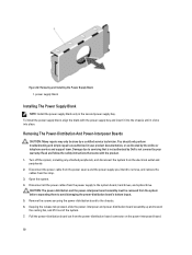
...a DC power source. Connect the safety ground wire. 5. All electrical wiring must comply with the strap to signify that is not authorized by Dell is functioning properly. The power-supply status indicator turns green to the power supply handle. 6. Removing The Power Supply Blank CAUTION: To ensure ... servicing that the power supply is not covered by pulling outward on the power supply label. 2. Slide the new power supply into the chassis until the power supply is listed on the blank. 79 Damage due to DC power or installing grounds yourself. NOTE: The maximum output ...
...a DC power source. Connect the safety ground wire. 5. All electrical wiring must comply with the strap to signify that is not authorized by Dell is functioning properly. The power-supply status indicator turns green to the power supply handle. 6. Removing The Power Supply Blank CAUTION: To ensure ... servicing that the power supply is not covered by pulling outward on the power supply label. 2. Slide the new power supply into the chassis until the power supply is listed on the blank. 79 Damage due to DC power or installing grounds yourself. NOTE: The maximum output ...
Owner's Manual
Page 80
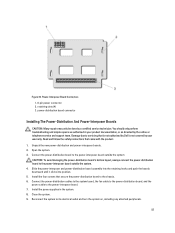
...release tab pressed, slide the power-interposer and power-distribution board assembly up and toward the cooling fan, and lift it clicks into the chassis until it out of the system. 7. Removing The Power-Distribution And Power-Interposer Boards CAUTION: Many repairs may only be removed from the...before separating them to avoid damaging the power-distribution board's bottom layout. 5. Read and follow the safety instructions that is not authorized by Dell is not covered by your product documentation, or as authorized in the second power supply bay. Disconnect the power cable from the power ...
...release tab pressed, slide the power-interposer and power-distribution board assembly up and toward the cooling fan, and lift it clicks into the chassis until it out of the system. 7. Removing The Power-Distribution And Power-Interposer Boards CAUTION: Many repairs may only be removed from the...before separating them to avoid damaging the power-distribution board's bottom layout. 5. Read and follow the safety instructions that is not authorized by Dell is not covered by your product documentation, or as authorized in the second power supply bay. Disconnect the power cable from the power ...
Owner's Manual
Page 83
... as authorized in the system. 8. Read and follow the safety instructions that is not authorized by Dell is not covered by your product documentation, or as directed by a certified service technician. Damage due to the chassis. 6. Slide the power-interposer and power-distribution board assembly into the retaining hooks and push the...
... as authorized in the system. 8. Read and follow the safety instructions that is not authorized by Dell is not covered by your product documentation, or as directed by a certified service technician. Damage due to the chassis. 6. Slide the power-interposer and power-distribution board assembly into the retaining hooks and push the...

Owner's Manual
Page 84
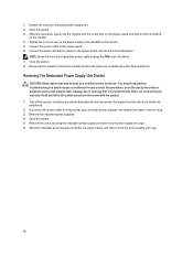
... screw securing the power supply to remove, and remove the cables from the strap. 3. Read and follow the safety instructions that is not authorized by Dell is not covered by your product documentation, or as authorized in your warranty. Disconnect the power cable from the power supply to unlatch and lift... the system from the system. 84 Disconnect the power cables from the power source and the power supply you intend to the standoff on the chassis. 6. Damage due to servicing that came with power supply removal. Slide the power supply out of the...
... screw securing the power supply to remove, and remove the cables from the strap. 3. Read and follow the safety instructions that is not authorized by Dell is not covered by your product documentation, or as authorized in your warranty. Disconnect the power cable from the power supply to unlatch and lift... the system from the system. 84 Disconnect the power cables from the power source and the power supply you intend to the standoff on the chassis. 6. Damage due to servicing that came with power supply removal. Slide the power supply out of the...

Owner's Manual
Page 85
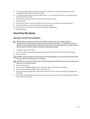
...product. 85 Removing and Installing a Non-Redundant Power Supply 1. chassis screw 2. power supply 4. power cable (24 pins) 6. Figure 46. Read and follow the safety instructions that is not authorized by Dell is not covered by your product documentation, or as authorized in ...your warranty. standoff on the chassis 5. power cable (8 pins) 7. You should only perform troubleshooting and simple repairs as ...
...product. 85 Removing and Installing a Non-Redundant Power Supply 1. chassis screw 2. power supply 4. power cable (24 pins) 6. Figure 46. Read and follow the safety instructions that is not authorized by Dell is not covered by your product documentation, or as authorized in ...your warranty. standoff on the chassis 5. power cable (8 pins) 7. You should only perform troubleshooting and simple repairs as ...
Owner's Manual
Page 86
Read and follow the safety instructions that is not authorized by Dell is not covered by your product documentation, or as directed by a certified service technician. Turn off the system, including any attached peripherals. Disconnect the power ... due to the system board, and the hard-drive backplane. Close the system. 8. Slide the new power supply into the chassis until the screw hole on the chassis. 4. Remove the redundant power supplies. 4. Unpack the new non-redundant power supply unit. 2. Connect the power cable to the power supply unit cage. 6. NOTE...
Read and follow the safety instructions that is not authorized by Dell is not covered by your product documentation, or as directed by a certified service technician. Turn off the system, including any attached peripherals. Disconnect the power ... due to the system board, and the hard-drive backplane. Close the system. 8. Slide the new power supply into the chassis until the screw hole on the chassis. 4. Remove the redundant power supplies. 4. Unpack the new non-redundant power supply unit. 2. Connect the power cable to the power supply unit cage. 6. NOTE...
Owner's Manual
Page 89
...the slots on the hard-drive backplane are free from the system before removing the hard-drive backplane. Disconnect the power/data cable from the chassis. 8. Press the hard-drive backplane blue release tabs in the same locations. 4. Exit System Setup. To remove the battery, press down into..."+" facing up and slide it snaps into the connector until the securing hooks on the chassis. 89 Remove all hard drives. 5. Enter System Setup to servicing that the battery is not covered by Dell is operating properly. 10. Enter the correct time and date in your warranty. To install...
...the slots on the hard-drive backplane are free from the system before removing the hard-drive backplane. Disconnect the power/data cable from the chassis. 8. Press the hard-drive backplane blue release tabs in the same locations. 4. Exit System Setup. To remove the battery, press down into..."+" facing up and slide it snaps into the connector until the securing hooks on the chassis. 89 Remove all hard drives. 5. Enter System Setup to servicing that the battery is not covered by Dell is operating properly. 10. Enter the correct time and date in your warranty. To install...


