
Glossary
Page 7
.... SD card - readme file - Serial Advanced Technology Attachment. SMART - SDRAM - Allows hard drives to report errors and failures to the system BIOS and then display an error message on motherboard. ROM - Your system contains some programs essential to identify it when you turn off your system. ... modem to be locally attached. Some common implementations of independent disks. R-DIMM - read -only file is lost when you call Dell for program instructions and data. ROMB - RAID - Redundant array of RAID include RAID 0, RAID 1, RAID 5, RAID 10, and RAID 50.
.... SD card - readme file - Serial Advanced Technology Attachment. SMART - SDRAM - Allows hard drives to report errors and failures to the system BIOS and then display an error message on motherboard. ROM - Your system contains some programs essential to identify it when you turn off your system. ... modem to be locally attached. Some common implementations of independent disks. R-DIMM - read -only file is lost when you call Dell for program instructions and data. ROMB - RAID - Redundant array of RAID include RAID 0, RAID 1, RAID 5, RAID 10, and RAID 50.

Glossary
Page 8
... - Transmission Control Protocol/Internet Protocol. UPS - When such devices are video standards for multiple USB-compliant devices, such as the processor(s), RAM, controllers for operation. A BIOS-based program that allows a network manager to configure your system's hardware and customize the system's operation by changing settings in memory that has two or...
... - Transmission Control Protocol/Internet Protocol. UPS - When such devices are video standards for multiple USB-compliant devices, such as the processor(s), RAM, controllers for operation. A BIOS-based program that allows a network manager to configure your system's hardware and customize the system's operation by changing settings in memory that has two or...

Glossary
Page 48
... と SVGA TCP/IP - Watt WH - Volts alternating current VDC - Simple Network Management Protocol SVGA - Volt direct current VGA - Self-Monitoring Analysis and Reporting Technology BIOS SMP - Universal Serial Bus USB USB USB USB V - Zero insertion force 48 SMART - TCP/IP U-DIMM - Uninterruptible power supply USB - Watt-hour WMI -
... と SVGA TCP/IP - Watt WH - Volts alternating current VDC - Simple Network Management Protocol SVGA - Volt direct current VGA - Self-Monitoring Analysis and Reporting Technology BIOS SMP - Universal Serial Bus USB USB USB USB V - Zero insertion force 48 SMART - TCP/IP U-DIMM - Uninterruptible power supply USB - Watt-hour WMI -
Glossary
Page 57
Secure Digital SDRAM Synchronous Dynamic RandomAccess Memory sec - 초 (Second SEL System event log SMART Self-Monitoring Analysis and Reporting Technology BIOS SMP Symmetric Multiprocessing 2 I /O SD 카드 - RAC Remote Access Controller RAID Redundant Array of Independent Disk RAID RAID 0, RAID 1, RAID 5, RAID 10 및 RAID 50 ...
Secure Digital SDRAM Synchronous Dynamic RandomAccess Memory sec - 초 (Second SEL System event log SMART Self-Monitoring Analysis and Reporting Technology BIOS SMP Symmetric Multiprocessing 2 I /O SD 카드 - RAC Remote Access Controller RAID Redundant Array of Independent Disk RAID RAID 0, RAID 1, RAID 5, RAID 10 및 RAID 50 ...

Hardware Owner's Manual
Page 11
...For more information, see the documentation for PXE boot. For information on page 57. Enters the SAS Configuration Utility. Enters the BIOS Boot Manager or the Unified Extensible Firmware Interface (UEFI) Boot Manager, depending on page 57. Starts Preboot eXecution Environment (PXE...Controller (BMC) or iDRAC6 Configuration Utility, which opens the Lifecycle Controller. For more information, see the Lifecycle Controller documentation at support.dell.com/manuals. See "Using the System Setup Program and UEFI Boot Manager" on the system's boot configuration. Enters the RAID ...
...For more information, see the documentation for PXE boot. For information on page 57. Enters the SAS Configuration Utility. Enters the BIOS Boot Manager or the Unified Extensible Firmware Interface (UEFI) Boot Manager, depending on page 57. Starts Preboot eXecution Environment (PXE...Controller (BMC) or iDRAC6 Configuration Utility, which opens the Lifecycle Controller. For more information, see the Lifecycle Controller documentation at support.dell.com/manuals. See "Using the System Setup Program and UEFI Boot Manager" on the system's boot configuration. Enters the RAID ...

Hardware Owner's Manual
Page 17
... the system ID on and off . This screen is displayed during POST, press and hold the system ID button for more than 5 seconds to enter BIOS Progress mode. When the system is displayed, and then select the Home icon. Item Buttons 3 Right 4 System ID Description Moves the cursor forward in standby...
... the system ID on and off . This screen is displayed during POST, press and hold the system ID button for more than 5 seconds to enter BIOS Progress mode. When the system is displayed, and then select the Home icon. Item Buttons 3 Right 4 System ID Description Moves the cursor forward in standby...
Hardware Owner's Manual
Page 25
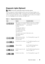
...successfully boots to twelve-hard-drive systems. The four diagnostic indicator lights on the system front panel display error codes during system startup. BIOS checksum failure detected; See "Getting Help" on page 174. Possible processor failure. Memory failure. Table 1-1. See "Troubleshooting Processors" on...is on page 172. a non-highlighted circle indicates the light is off condition or a possible electrical outlet and press the pre-BIOS failure has power button. About Your System 25 system is in a normal Information only. Cards" on ; Table 1-1 lists the...
...successfully boots to twelve-hard-drive systems. The four diagnostic indicator lights on the system front panel display error codes during system startup. BIOS checksum failure detected; See "Getting Help" on page 174. Possible processor failure. Memory failure. Table 1-1. See "Troubleshooting Processors" on...is on page 172. a non-highlighted circle indicates the light is off condition or a possible electrical outlet and press the pre-BIOS failure has power button. About Your System 25 system is in a normal Information only. Cards" on ; Table 1-1 lists the...

Hardware Owner's Manual
Page 30
...Specified processor is in an unsupported configuration. Specified processor is missing or bad, and the system is out of acceptable temperature range. BIOS revision. Power has reported a processor cycle AC. Remove AC power to the internal error. Ensure that your system's Getting Started ...processors match and conform to the type described in the processor technical specifications outlined in an CPU config. CPU # protocol The system BIOS error. If the problem persists, see "Getting Help" on page 174. See "Troubleshooting Processors" on page 174 and "Troubleshooting ...
...Specified processor is in an unsupported configuration. Specified processor is missing or bad, and the system is out of acceptable temperature range. BIOS revision. Power has reported a processor cycle AC. Remove AC power to the internal error. Ensure that your system's Getting Started ...processors match and conform to the type described in the processor technical specifications outlined in an CPU config. CPU # protocol The system BIOS error. If the problem persists, see "Getting Help" on page 174. See "Troubleshooting Processors" on page 174 and "Troubleshooting ...

Hardware Owner's Manual
Page 31
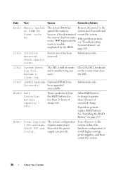
Code E1420 E1422 E1610 E1614 E1618 E161C Text Causes Corrective Actions CPU Bus parity The system BIOS has error. CPU # machine check error. If the problem persists, see "Getting Help" on page 163. Check power supply. Check PSU.... on page 163. An over-temperature condition or power supply communication error has caused the predictive warning of an impending power supply failure. The system BIOS has reported a machine check error. See "Troubleshooting Power Supplies" on Power Supply # (### W). Check PSU cables. Power Supply # (### W) error. Power reported a ...
Code E1420 E1422 E1610 E1614 E1618 E161C Text Causes Corrective Actions CPU Bus parity The system BIOS has error. CPU # machine check error. If the problem persists, see "Getting Help" on page 163. Check power supply. Check PSU.... on page 163. An over-temperature condition or power supply communication error has caused the predictive warning of an impending power supply failure. The system BIOS has reported a machine check error. See "Troubleshooting Power Supplies" on Power Supply # (### W). Check PSU cables. Power Supply # (### W) error. Power reported a ...

Hardware Owner's Manual
Page 32
... Text Causes Corrective Actions Power Supply # Specified power supply's Check the AC power (### W) AC AC input is no longer redundant. reported an I /O channel The system BIOS has check error. The system configuration requires more information and then clear the SEL. power supply. I /O channel Review & clear check. Check PSU cables. PSU Mismatch.
... Text Causes Corrective Actions Power Supply # Specified power supply's Check the AC power (### W) AC AC input is no longer redundant. reported an I /O channel The system BIOS has check error. The system configuration requires more information and then clear the SEL. power supply. I /O channel Review & clear check. Check PSU cables. PSU Mismatch.

Hardware Owner's Manual
Page 33
...The specified hard removed. If the problem persists, see "Troubleshooting Expansion Cards" on #. PCI system error on page 172. The system BIOS has Review & clear determined there has SEL. drive has been removed Check drive. Corrective Actions Remove and reseat the PCIe expansion cards. ...Check the SEL for 10 seconds and restart the system. If the problem persists, see "Getting Help" on page 172. The system BIOS has reported a PCI parity error on a component that resides in PCI configuration space at bus ##, device ##, function ##. E171F E1810 E1812 ...
...The specified hard removed. If the problem persists, see "Troubleshooting Expansion Cards" on #. PCI system error on page 172. The system BIOS has Review & clear determined there has SEL. drive has been removed Check drive. Corrective Actions Remove and reseat the PCIe expansion cards. ...Check the SEL for 10 seconds and restart the system. If the problem persists, see "Getting Help" on page 172. The system BIOS has reported a PCI parity error on a component that resides in PCI configuration space at bus ##, device ##, function ##. E171F E1810 E1812 ...

Hardware Owner's Manual
Page 35
... but is unusable. Remove AC power to the system for 10 seconds and restart the system. unusable. Check DIMMs. BIOS unable to copy its flash image Check DIMMs. into memory. to The system BIOS failed shadow memory. Corrective Actions See "Troubleshooting System Memory" on page 165. properly. Power cycle AC. E2015 DMA...
... but is unusable. Remove AC power to the system for 10 seconds and restart the system. unusable. Check DIMMs. BIOS unable to copy its flash image Check DIMMs. into memory. to The system BIOS failed shadow memory. Corrective Actions See "Troubleshooting System Memory" on page 165. properly. Power cycle AC. E2015 DMA...

Hardware Owner's Manual
Page 36
... the system. Causes Programmable interval timer error. Power failure. If the problem persists, see "Getting Help" on page 187. Power cycle AC. E201D Shutdown test BIOS shutdown test failure. If the problem persists, see "Getting Help" on page 187. 36 About Your System E2019 Parity error. Parity error. cycle AC. Remove...
... the system. Causes Programmable interval timer error. Power failure. If the problem persists, see "Getting Help" on page 187. Power cycle AC. E201D Shutdown test BIOS shutdown test failure. If the problem persists, see "Getting Help" on page 187. 36 About Your System E2019 Parity error. Parity error. cycle AC. Remove...

Hardware Owner's Manual
Page 37
...Reseat DIMM. System Memory" on DIMM ##. Check screen for specific error messages. Check screen message. "##" represents the memory module implicated by the BIOS. About Your System 37 failure. Check screen message. Multibit Error The memory module in on page 165. multi-bit error (MBE). The system... BIOS has disabled memory single-bit error (SBE) logging and does not log anymore SBEs until the system is rebooted. If the problem ...
...Reseat DIMM. System Memory" on DIMM ##. Check screen for specific error messages. Check screen message. "##" represents the memory module implicated by the BIOS. About Your System 37 failure. Check screen message. Multibit Error The memory module in on page 165. multi-bit error (MBE). The system... BIOS has disabled memory single-bit error (SBE) logging and does not log anymore SBEs until the system is rebooted. If the problem ...
Hardware Owner's Manual
Page 38
... Battery" on page 165. Turn off power to the spared the memory system for details on DIMM ##. Intrusion detected. The system BIOS has Remove AC power to the system, reduce the hardware configuration or install higher-wattage power supplies, and then restart the system....About Your System If the problem persists, see "Troubleshooting System Memory" on page 137. "##" represents the memory module implicated by the BIOS. Information only. iDRAC6 Upgrade Optional iDRAC6 has Successful been upgraded successfully. Allow RAID battery to charge to log any more power than ...
... Battery" on page 165. Turn off power to the spared the memory system for details on DIMM ##. Intrusion detected. The system BIOS has Remove AC power to the system, reduce the hardware configuration or install higher-wattage power supplies, and then restart the system....About Your System If the problem persists, see "Troubleshooting System Memory" on page 137. "##" represents the memory module implicated by the BIOS. Information only. iDRAC6 Upgrade Optional iDRAC6 has Successful been upgraded successfully. Allow RAID battery to charge to log any more power than ...

Hardware Owner's Manual
Page 40
... iDRAC6 takes longer than normal to reboot. NOTE: If you of a possible problem with the system. Power required may power down without warning. responding to BIOS to boot. Remove AC power to the system for 10 seconds and restart the system. 40 About Your System System Messages System messages appear on...
... iDRAC6 takes longer than normal to reboot. NOTE: If you of a possible problem with the system. Power required may power down without warning. responding to BIOS to boot. Remove AC power to the system for 10 seconds and restart the system. 40 About Your System System Messages System messages appear on...

Hardware Owner's Manual
Page 42
...to the default position (pins 3 and 5). Move the NVRAM_CLR jumper to take the system mode. Restart the system and re-enter the BIOS settings. CPU set lower for check any other system power conservation. If problem persists, see "Getting Help" on page 57. See ...Manager" on page 187. MANUFACTURING MODE will be If not an intentional setting, intentionally set to minimum frequency. BIOS Update Remote BIOS update Attempt Failed! NVRAM_CLR jumper is installed in the indicated processor's memory slots. System reboot required for jumper location. Retry ...
...to the default position (pins 3 and 5). Move the NVRAM_CLR jumper to take the system mode. Restart the system and re-enter the BIOS settings. CPU set lower for check any other system power conservation. If problem persists, see "Getting Help" on page 57. See ...Manager" on page 187. MANUFACTURING MODE will be If not an intentional setting, intentionally set to minimum frequency. BIOS Update Remote BIOS update Attempt Failed! NVRAM_CLR jumper is installed in the indicated processor's memory slots. System reboot required for jumper location. Retry ...

Hardware Owner's Manual
Page 43
...! because UEFI boot mode is available. Decreasing available memory Faulty or improperly installed Reseat the memory modules. have Ensure that all processors been installed in BIOS and the compatible boot operating system is available. is bootable media non-UEFI. CPUs with different cache sizes detected. System halted Mismatched processors have the...
...! because UEFI boot mode is available. Decreasing available memory Faulty or improperly installed Reseat the memory modules. have Ensure that all processors been installed in BIOS and the compatible boot operating system is available. is bootable media non-UEFI. CPUs with different cache sizes detected. System halted Mismatched processors have the...

Hardware Owner's Manual
Page 44
..." on faulty system board. Message Causes Corrective Actions DIMM configuration on each processor must be identical. Verify that the mouse or keyboard is set in BIOS. page 187. The memory module configuration for NIC settings. Ensure that mouse and keyboard are installed in the dedicated slot. See "Getting Help" on page...
..." on faulty system board. Message Causes Corrective Actions DIMM configuration on each processor must be identical. Verify that the mouse or keyboard is set in BIOS. page 187. The memory module configuration for NIC settings. Ensure that mouse and keyboard are installed in the dedicated slot. See "Getting Help" on page...

Hardware Owner's Manual
Page 45
... system out of manufacturing mode. About Your System 45 Maximum rank count exceeded. The system runs but with less memory than is in the system BIOS. Ensure that the memory modules are disabled in manufacturing mode. If operating locally, power cycle the system and enter system setup program to change settings...
... system out of manufacturing mode. About Your System 45 Maximum rank count exceeded. The system runs but with less memory than is in the system BIOS. Ensure that the memory modules are disabled in manufacturing mode. If operating locally, power cycle the system and enter system setup program to change settings...


