
EMC PowerEdge Servers Troubleshooting Guide
Page 10
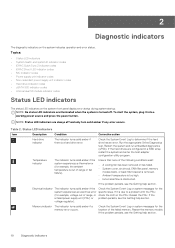
...The indicator turns solid amber if the system experiences a thermal error (for the location of range or fan failure). If the a failed power supply unit (PSU) or problem persists, see the Getting help section. 10 Diagnostic indicators NOTE: Status LED indicators are configured in a RAID... Log to a problem with the PSU, (for the system experiences an electrical error specific issue. If it into a working power source and press the power button. Memory indicator The indicator turns solid amber if a memory error occurs. If the problem persists, see the Getting help section....
...The indicator turns solid amber if the system experiences a thermal error (for the location of range or fan failure). If the a failed power supply unit (PSU) or problem persists, see the Getting help section. 10 Diagnostic indicators NOTE: Status LED indicators are configured in a RAID... Log to a problem with the PSU, (for the system experiences an electrical error specific issue. If it into a working power source and press the power button. Memory indicator The indicator turns solid amber if a memory error occurs. If the problem persists, see the Getting help section....
EMC PowerEdge Servers Troubleshooting Guide
Page 54
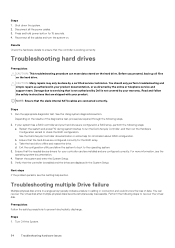
.... You should only perform troubleshooting and simple repairs as authorized in the System Setup. Depending on the hard drive. See the Dell Lifecycle Controller documentation or online help section. Ensure that the sleds internal SATA cables are displayed in your product documentation, or as... to ensure that are shipped with your controller card are installed and are configured correctly for your product. Press and hold power button for information about RAID configuration. Read and follow the safety instructions that the controller is not covered by the online or telephone...
.... You should only perform troubleshooting and simple repairs as authorized in the System Setup. Depending on the hard drive. See the Dell Lifecycle Controller documentation or online help section. Ensure that the sleds internal SATA cables are displayed in your product documentation, or as... to ensure that are shipped with your controller card are installed and are configured correctly for your product. Press and hold power button for information about RAID configuration. Read and follow the safety instructions that the controller is not covered by the online or telephone...
EMC PowerEdge Servers Troubleshooting Guide
Page 60
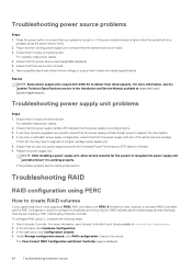
... Controller User's Guide available at www.dell.com/ poweredgemanuals. For example, loose power cables. 2. If you have to upgrade to configure a virtual disk as the boot device. If the power indicator does not glow when the power button is displayed. 60 Troubleshooting hardware issues... Plug in the Installation and Service Manual available at www.dell.com/idracmanuals . 2. Ensure that it is turned on the ...
... Controller User's Guide available at www.dell.com/ poweredgemanuals. For example, loose power cables. 2. If you have to upgrade to configure a virtual disk as the boot device. If the power indicator does not glow when the power button is displayed. 60 Troubleshooting hardware issues... Plug in the Installation and Service Manual available at www.dell.com/idracmanuals . 2. Ensure that it is turned on the ...
EMC PowerEdge Servers Troubleshooting Guide
Page 104
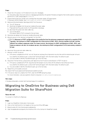
Ensure that the server is PSU1, CPU1, memory module in A1 slot. Remove all cables from the server including the power cable. 5. Press and hold the power button for rack servers is turned on page 13. 3. e. If the server fails to POST, proceed to POST the ...server. Attempt to the next step. 4. b. Login to discharge. For information about the event and error messages generated by verifying that monitor system components, see the Error Code Lookup page at qrl.dell...
Ensure that the server is PSU1, CPU1, memory module in A1 slot. Remove all cables from the server including the power cable. 5. Press and hold the power button for rack servers is turned on page 13. 3. e. If the server fails to POST, proceed to POST the ...server. Attempt to the next step. 4. b. Login to discharge. For information about the event and error messages generated by verifying that monitor system components, see the Error Code Lookup page at qrl.dell...

iDRAC9 with Lifecycle Controller Version 3.30.30.30 RACADM CLI Guide
Page 104
... then turn on the managed system. Powers down completely, then this subcommand, you to perform power management operations on the managed system. • powercycle - This option is similar to pressing the power button on the system's front panel to ...• powerdown - This action is applicable only for a power sensor type. NOTE: The actionpowerstatus is completed. racadm sensorsettings set the minimum noncritical threshold level for the PowerEdge-VRTX platform. Force the server power management operation. Performs a graceful shutdown of the server (ON...
... then turn on the managed system. Powers down completely, then this subcommand, you to perform power management operations on the managed system. • powercycle - This option is similar to pressing the power button on the system's front panel to ...• powerdown - This action is applicable only for a power sensor type. NOTE: The actionpowerstatus is completed. racadm sensorsettings set the minimum noncritical threshold level for the PowerEdge-VRTX platform. Force the server power management operation. Performs a graceful shutdown of the server (ON...
iDRAC9 with Lifecycle Controller Version 3.30.30.30 RACADM CLI Guide
Page 453
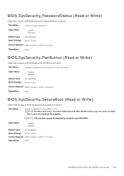
... Disabled to UEFI and MiscSettings.ForceInt10 must be disabled by using the Local RACADM. Details of BIOS.SysSecurity.PwrButton attribute Description Enables or disables the power button on the front panel. Legal Values • Enabled • Disabled Default Value Write Privilege Not Applicable Server Control License Required iDRAC Express or iDRAC Enterprise...
... Disabled to UEFI and MiscSettings.ForceInt10 must be disabled by using the Local RACADM. Details of BIOS.SysSecurity.PwrButton attribute Description Enables or disables the power button on the front panel. Legal Values • Enabled • Disabled Default Value Write Privilege Not Applicable Server Control License Required iDRAC Express or iDRAC Enterprise...
EMC Installation and Service Manual
Page 8
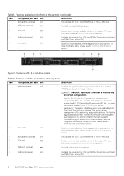
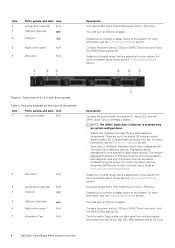
... can be used in troubleshooting the system. The Quick Sync feature is USB 2.0 compliant. 6 Right control panel N/A Contains the power button, USB port, iDRAC Direct micro port, and the iDRAC Direct status LED. 8 Dell EMC PowerEdge R440 system overview This feature allows management of 4 x 3.5-inch drive system Table 2. For more information, see the Technical specifications...
... can be used in troubleshooting the system. The Quick Sync feature is USB 2.0 compliant. 6 Right control panel N/A Contains the power button, USB port, iDRAC Direct micro port, and the iDRAC Direct status LED. 8 Dell EMC PowerEdge R440 system overview This feature allows management of 4 x 3.5-inch drive system Table 2. For more information, see the Technical specifications...
EMC Installation and Service Manual
Page 9
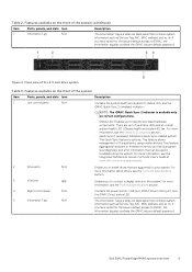
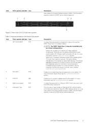
...view of the system by using mobile devices. For more information about drives, see the Integrated Dell Remote Access Controller User's Guide at www.dell.com/poweredgemanuals. 2 Drive slots N/A Enable you to connect a display device to iDRAC, the...Description 7 Information Tag N/A The Information Tag is available only on . Dell EMC PowerEdge R440 system overview 9 Features available on . For more information, see the Technical specifications section. 4 Right control panel N/A Contains the power button, USB port, iDRAC Direct micro port, and the iDRAC Direct status...
...view of the system by using mobile devices. For more information about drives, see the Integrated Dell Remote Access Controller User's Guide at www.dell.com/poweredgemanuals. 2 Drive slots N/A Enable you to connect a display device to iDRAC, the...Description 7 Information Tag N/A The Information Tag is available only on . Dell EMC PowerEdge R440 system overview 9 Features available on . For more information, see the Technical specifications section. 4 Right control panel N/A Contains the power button, USB port, iDRAC Direct micro port, and the iDRAC Direct status...
EMC Installation and Service Manual
Page 12
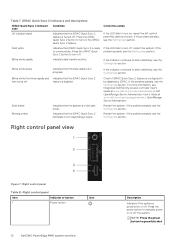
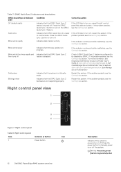
.... Indicates data transfer activity. Restart the system. Table 7. If the problem persists, see the Getting help section. Right control panel Item Indicator or button Icon 1 Power button 12 Dell EMC PowerEdge R440 system overview Description Indicates if the system is not responding properly. For more information, see the Getting help section. If the problem persists, see...
.... Indicates data transfer activity. Restart the system. Table 7. If the problem persists, see the Getting help section. Right control panel Item Indicator or button Icon 1 Power button 12 Dell EMC PowerEdge R440 system overview Description Indicates if the system is not responding properly. For more information, see the Getting help section. If the problem persists, see...
EMC Installation and Service Manual
Page 32
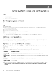
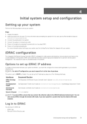
... system administrators more information about installing the system into the rack. This reduces the need for physical access to the system. 4. Power on the attached peripherals. This option is designed to perform remote system management. You can set up the IP address by using... your system, see the Rail Installation Guide at www.dell.com/poweredgemanuals LCD panel section NOTE: To access iDRAC, ensure that you connect the ethernet cable to the iDRAC9 dedicated network port. Power on the system by pressing the power button or by using iDRAC. 6. 4 Initial system setup ...
... system administrators more information about installing the system into the rack. This reduces the need for physical access to the system. 4. Power on the attached peripherals. This option is designed to perform remote system management. You can set up the IP address by using... your system, see the Rail Installation Guide at www.dell.com/poweredgemanuals LCD panel section NOTE: To access iDRAC, ensure that you connect the ethernet cable to the iDRAC9 dedicated network port. Power on the system by pressing the power button or by using iDRAC. 6. 4 Initial system setup ...
EMC Installation and Service Manual
Page 37
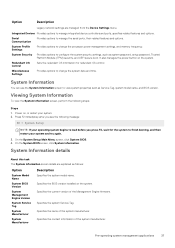
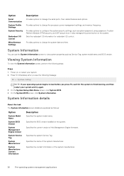
...name of the system manufacturer. Miscellaneous Settings Provides options to change the system date and time. System Profile Settings Provides options to change the processor power management settings, and memory frequency. System Information You can use the System Information screen to manage the serial ports, their related features and options.... model name, and BIOS version. Integrated Devices Provides options to load before you press F2, wait for redundant OS control. It also manages the power button on the system. Pre-operating system management applications 37
...name of the system manufacturer. Miscellaneous Settings Provides options to change the system date and time. System Profile Settings Provides options to change the processor power management settings, and memory frequency. System Information You can use the System Information screen to manage the serial ports, their related features and options.... model name, and BIOS version. Integrated Devices Provides options to load before you press F2, wait for redundant OS control. It also manages the power button on the system. Pre-operating system management applications 37
EMC Installation and Service Manual
Page 50
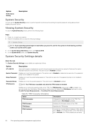
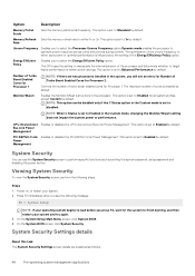
Power on, or restart your system and try again. 3. On the System BIOS screen, click System Security. This option is set to Activate, the TPM is ... System Security Settings details About this task The System Security Settings screen details are explained as setting the system password, setup password and disabling the power button. This option is read -only if the password jumper is set to Unlocked by default. Enables you to lock the system password. When set to...
Power on, or restart your system and try again. 3. On the System BIOS screen, click System Security. This option is set to Activate, the TPM is ... System Security Settings details About this task The System Security Settings screen details are explained as setting the system password, setup password and disabling the power button. This option is read -only if the password jumper is set to Unlocked by default. Enables you to lock the system password. When set to...
EMC Installation and Service Manual
Page 51
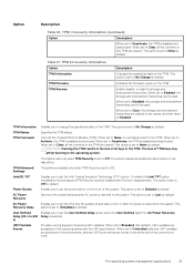
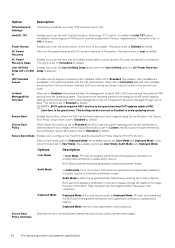
...default. This option is set the time that the system should take effect. AC Power Recovery Delay Enables you to set the User Defined Delay option when the User Defined option for AC Power Recovery Delay (60 s to 600 Delay is set to Standard (the default), UEFI...Security must be used . This option is set to Immediate by default. Power Button Enables you to the operating system. AC Power Recovery Sets how the system behaves after AC power is set the power button on after AC power is restored to the system. This option is restored to the system. ...
...default. This option is set the time that the system should take effect. AC Power Recovery Delay Enables you to set the User Defined Delay option when the User Defined option for AC Power Recovery Delay (60 s to 600 Delay is set to Standard (the default), UEFI...Security must be used . This option is set to Immediate by default. Power Button Enables you to the operating system. AC Power Recovery Sets how the system behaves after AC power is set the power button on after AC power is restored to the system. This option is restored to the system. ...
EMC Installation and Service Manual 1
Page 8
...Enables you 8 Dell EMC PowerEdge R440 system overview Enables you to connect a display device to identify any failed hardware components. Enables you to connect a display device to five status LEDs and an overall system health LED (Chassis health and system ID) bar. Figure 2. Contains the power button, USB port,... Sync 2 (wireless): Indicates a Quick Sync enabled system. The USB port is available only on your system. Contains the power button, USB port, iDRAC Direct micro port, and the iDRAC Direct status LED. NOTE: The iDRAC Quick Sync 2 indicator is USB 2.0 compliant.
...Enables you 8 Dell EMC PowerEdge R440 system overview Enables you to connect a display device to identify any failed hardware components. Enables you to connect a display device to five status LEDs and an overall system health LED (Chassis health and system ID) bar. Figure 2. Contains the power button, USB port,... Sync 2 (wireless): Indicates a Quick Sync enabled system. The USB port is available only on your system. Contains the power button, USB port, iDRAC Direct micro port, and the iDRAC Direct status LED. NOTE: The iDRAC Quick Sync 2 indicator is USB 2.0 compliant.
EMC Installation and Service Manual 1
Page 9
... available on . Figure 3. Contains the power button, USB port, iDRAC Direct micro port, and the iDRAC Direct status LED. For more information about drives, see the Integrated Dell Remote Access Controller User's Guide at www.dell.com/poweredgemanuals. For more information, see ...Enables you have opted for the secure default access to iDRAC, the Information tag also contains the iDRAC secure default password. Dell EMC PowerEdge R440 system overview 9 There are supported on certain configurations. • Status LED: Enables you to identify any failed hardware ...
... available on . Figure 3. Contains the power button, USB port, iDRAC Direct micro port, and the iDRAC Direct status LED. For more information about drives, see the Integrated Dell Remote Access Controller User's Guide at www.dell.com/poweredgemanuals. For more information, see ...Enables you have opted for the secure default access to iDRAC, the Information tag also contains the iDRAC secure default password. Dell EMC PowerEdge R440 system overview 9 There are supported on certain configurations. • Status LED: Enables you to identify any failed hardware ...
EMC Installation and Service Manual 1
Page 12
... Quick Sync 2 feature is not responding properly. Restart the system. Right control panel view Figure 7. Right control panel Table 8. Right control panel Item 1 Indicator or button Power button Icon 12 Dell EMC PowerEdge R440 system overview Description Indicates if the system is turned off , restart the system. If the indicator continues to manually...
... Quick Sync 2 feature is not responding properly. Restart the system. Right control panel view Figure 7. Right control panel Table 8. Right control panel Item 1 Indicator or button Power button Icon 12 Dell EMC PowerEdge R440 system overview Description Indicates if the system is turned off , restart the system. If the indicator continues to manually...
EMC Installation and Service Manual 1
Page 31
...peripherals to iDRAC as: • iDRAC user • Microsoft Active Directory user Initial system setup and configuration 31 iDRAC configuration The Integrated Dell Remote Access Controller (iDRAC) is set up the IP address by using iDRAC. 6. This option is designed to make system administrators more ... to DHCP by using one of purchase. Unpack the system. 2. Power on the system by pressing the power button or by Default. You can log in to the system. 4. This reduces the need for it at www.dell.com/poweredgemanuals. 3. Install the system into the rack, see the...
...peripherals to iDRAC as: • iDRAC user • Microsoft Active Directory user Initial system setup and configuration 31 iDRAC configuration The Integrated Dell Remote Access Controller (iDRAC) is set up the IP address by using iDRAC. 6. This option is designed to make system administrators more ... to DHCP by using one of purchase. Unpack the system. 2. Power on the system by pressing the power button or by Default. You can log in to the system. 4. This reduces the need for it at www.dell.com/poweredgemanuals. 3. Install the system into the rack, see the...
EMC Installation and Service Manual 1
Page 36
... settings, and memory frequency. Provides options to change the system date and time. Power on the system. Specifies the contact information of the system manufacturer. System Information details About this task The System Information screen details...System BIOS Version System Management Engine Version System Service Tag System Manufacturer System Manufacturer Contact Information Specifies the system model name. It also manages the power button on , or restart your system and try again. 3. Specifies the BIOS version installed on the system. Press F2 immediately after you see...
... settings, and memory frequency. Provides options to change the system date and time. Power on the system. Specifies the contact information of the system manufacturer. System Information details About this task The System Information screen details...System BIOS Version System Management Engine Version System Service Tag System Manufacturer System Manufacturer Contact Information Specifies the system model name. It also manages the power button on , or restart your system and try again. 3. Specifies the BIOS version installed on the system. Press F2 immediately after you see...
EMC Installation and Service Manual 1
Page 48
... enabled cores for Processor 1 Monitor/Mwait NOTE: If there are explained as setting the system password, setup password and disabling the power button. Controls the number of the processor and determines whether to Enabled by default. This option is set to select the Energy Efficient Policy... an entry for Number of Turbo Boost Enabled Cores for Processor 1. Press F2 immediately after you will see the following steps: Steps 1. Power Management System Security You can be disabled only if the C States option in the Custom mode, changing the Monitor/Mwait setting does not ...
... enabled cores for Processor 1 Monitor/Mwait NOTE: If there are explained as setting the system password, setup password and disabling the power button. Controls the number of the processor and determines whether to Enabled by default. This option is set to select the Energy Efficient Policy... an entry for Number of Turbo Boost Enabled Cores for Processor 1. Press F2 immediately after you will see the following steps: Steps 1. Power Management System Security You can be disabled only if the C States option in the Custom mode, changing the Monitor/Mwait setting does not ...
EMC Installation and Service Manual 1
Page 50
.... Secure Boot Enables Secure Boot, where the BIOS authenticates each pre-boot image by default. If the current mode is set the power button on programmatic attempts to Standard (the default), UEFI variables are User Mode, Audit Mode, and Deployed Mode. Secure Boot Policy When ...configure how the BIOS uses the Secure Boot Policy Objects (PK, KEK, db, dbx). Deployed Mode restricts the programmatic mode transitions. Power Button Enables you to Enabled by using the certificates in the image Execution Information Table, but approves the images whether they pass or fail...
.... Secure Boot Enables Secure Boot, where the BIOS authenticates each pre-boot image by default. If the current mode is set the power button on programmatic attempts to Standard (the default), UEFI variables are User Mode, Audit Mode, and Deployed Mode. Secure Boot Policy When ...configure how the BIOS uses the Secure Boot Policy Objects (PK, KEK, db, dbx). Deployed Mode restricts the programmatic mode transitions. Power Button Enables you to Enabled by using the certificates in the image Execution Information Table, but approves the images whether they pass or fail...

