
Glossary
Page 1
Dell™ Glossary NOTE: For additional information on storage terminology, visit the Storage Networking Industry Association's website at www.snia.org and click on a regular basis. ... - bootable media - Celsius. A fast storage area that is located. ambient temperature - The temperature of data or instructions for security or tracking purposes. A CD, diskette, or USB memory key that keeps a copy of the area or room where the system is used to a system, usually by the DMTF. BTU - asset tag - Baseboard...
Dell™ Glossary NOTE: For additional information on storage terminology, visit the Storage Networking Industry Association's website at www.snia.org and click on a regular basis. ... - bootable media - Celsius. A fast storage area that is located. ambient temperature - The temperature of data or instructions for security or tracking purposes. A CD, diskette, or USB memory key that keeps a copy of the area or room where the system is used to a system, usually by the DMTF. BTU - asset tag - Baseboard...

Glossary
Page 5
...-hour(s). Megabyte(s); 1,048,576 bytes. MBps - memory address - A portable flash memory storage device integrated with a USB connector. mm - Millimeter(s). Your system's unique hardware number on a network. A system used for implementing shared storage on.... A small circuit board containing DRAM chips that contains the CIM schema definition. Megahertz. A managed system is monitored and managed using Dell OpenManage™ Server Administrator. Megabits per second. Mb - However, when referring to serve specific storage needs. memory key - MB...
...-hour(s). Megabyte(s); 1,048,576 bytes. MBps - memory address - A portable flash memory storage device integrated with a USB connector. mm - Millimeter(s). Your system's unique hardware number on a network. A system used for implementing shared storage on.... A small circuit board containing DRAM chips that contains the CIM schema definition. Megahertz. A managed system is monitored and managed using Dell OpenManage™ Server Administrator. Megabits per second. Mb - However, when referring to serve specific storage needs. memory key - MB...

Glossary
Page 8
... Setup program - Because the System Setup program is the same on a network hub or switch used . uplink port - USB - A BIOS-based program that allows a network manager to other hubs or switches without requiring a crossover cable. system configuration... An unregistered (unbuffered) DDR3 memory module. See memory key. 8 SMP - Symmetric multiprocessing. SNMP - A USB connector provides a single connection point for multiple USB-compliant devices, such as the processor(s), RAM, controllers for video adapters with greater resolution and color display capabilities ...
... Setup program - Because the System Setup program is the same on a network hub or switch used . uplink port - USB - A BIOS-based program that allows a network manager to other hubs or switches without requiring a crossover cable. system configuration... An unregistered (unbuffered) DDR3 memory module. See memory key. 8 SMP - Symmetric multiprocessing. SNMP - A USB connector provides a single connection point for multiple USB-compliant devices, such as the processor(s), RAM, controllers for video adapters with greater resolution and color display capabilities ...
Glossary
Page 15
SNMP SVGA VGA 和 SVGA TCP/IP Internet 协议。 TOE - TCP/IP U-DIMM DDR3 UPS USB USB USB USB USB V VAC VDC VGA VGA 和 SVGA W WH WMI - Windows Management Instrumentation 提供 CIM ZIF CPU I/O 9 USB 15
SNMP SVGA VGA 和 SVGA TCP/IP Internet 协议。 TOE - TCP/IP U-DIMM DDR3 UPS USB USB USB USB USB V VAC VDC VGA VGA 和 SVGA W WH WMI - Windows Management Instrumentation 提供 CIM ZIF CPU I/O 9 USB 15

Glossary
Page 48
Super video graphics array VGA と SVGA TCP/IP - TCP/IP U-DIMM - Uninterruptible power supply USB - Universal Serial Bus USB USB USB USB V - Symmetric multiprocessing I/O OS SNMP - Volts alternating current VDC - Transmission Control Protocol/Internet Protocol TOE - Volt VAC - Watt WH - Zero insertion force 48 Unregistered DDR3 UPS - ...
Super video graphics array VGA と SVGA TCP/IP - TCP/IP U-DIMM - Uninterruptible power supply USB - Universal Serial Bus USB USB USB USB V - Symmetric multiprocessing I/O OS SNMP - Volts alternating current VDC - Transmission Control Protocol/Internet Protocol TOE - Volt VAC - Watt WH - Zero insertion force 48 Unregistered DDR3 UPS - ...

Glossary
Page 58
... management station managed system) 은 Dell OpenManage™ Server Administrator x x y x z 58 SVGA Super Video Graphics Array VGA 와 SVGA TCP/IP Transmission Control Protocol/Internet Protocol TOE - TCP/IP TCP/IP Offload Engine U-DIMM DDR3 Unregistered(Unbuffered) DDR3 Memory Module UPS Uninterruptible Power Supply USB Universal Serial Bus USB USB USB USB V - 볼트 (Volt VAC...
... management station managed system) 은 Dell OpenManage™ Server Administrator x x y x z 58 SVGA Super Video Graphics Array VGA 와 SVGA TCP/IP Transmission Control Protocol/Internet Protocol TOE - TCP/IP TCP/IP Offload Engine U-DIMM DDR3 Unregistered(Unbuffered) DDR3 Memory Module UPS Uninterruptible Power Supply USB Universal Serial Bus USB USB USB USB V - 볼트 (Volt VAC...
Owner's Manual
Page 5
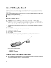
... The Optical Drive In Cabled Hard-Drive Systems 59 Cooling Fans...60 Removing A Cooling Fan...60 Installing A Cooling Fan...61 Internal USB Memory Key (Optional)...62 Replacing The Internal USB Key...62 Expansion Cards And Expansion-Card Risers...62 Expansion Card Installation Guidelines...63 Removing An Expansion Card...63 Installing An Expansion...
... The Optical Drive In Cabled Hard-Drive Systems 59 Cooling Fans...60 Removing A Cooling Fan...60 Installing A Cooling Fan...61 Internal USB Memory Key (Optional)...62 Replacing The Internal USB Key...62 Expansion Cards And Expansion-Card Risers...62 Expansion Card Installation Guidelines...63 Removing An Expansion Card...63 Installing An Expansion...
Owner's Manual
Page 6
...And Your System...101 Troubleshooting System Startup Failure...101 Troubleshooting External Connections...101 Troubleshooting The Video Subsystem...101 Troubleshooting A USB Device...101 Troubleshooting A Serial I/O Device...102 Troubleshooting A NIC...102 Troubleshooting A Wet System...102 Troubleshooting A ... Power Supplies...104 Troubleshooting Cooling Problems...104 Troubleshooting Cooling Fans...105 Troubleshooting System Memory...105 Troubleshooting An Internal USB Key...106 Troubleshooting An SD Card...106 Troubleshooting An Optical Drive...107 Troubleshooting A Tape Backup Unit...107...
...And Your System...101 Troubleshooting System Startup Failure...101 Troubleshooting External Connections...101 Troubleshooting The Video Subsystem...101 Troubleshooting A USB Device...101 Troubleshooting A Serial I/O Device...102 Troubleshooting A NIC...102 Troubleshooting A Wet System...102 Troubleshooting A ... Power Supplies...104 Troubleshooting Cooling Problems...104 Troubleshooting Cooling Fans...105 Troubleshooting System Memory...105 Troubleshooting An Internal USB Key...106 Troubleshooting An SD Card...106 Troubleshooting An Optical Drive...107 Troubleshooting A Tape Backup Unit...107...
Owner's Manual
Page 10
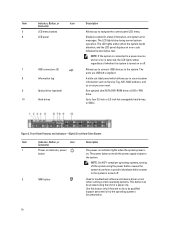
...displays an error code followed by the operating system's documentation. 10 The ports are USB 2.0-compliant. Item Indicator, Button, or Icon Description Connector 5 LCD menu buttons Allows you to connect USB devices to do so by qualified support personnel or by descriptive text. Figure 2. ... can be pressed using the power button causes the system to perform a graceful shutdown before power to the system is turned off . 7 USB connectors (2) 8 Information tag 9 Optical drive (optional) 10 Hard drives Allows you to the system. Use this button only if directed to...
...displays an error code followed by the operating system's documentation. 10 The ports are USB 2.0-compliant. Item Indicator, Button, or Icon Description Connector 5 LCD menu buttons Allows you to connect USB devices to do so by qualified support personnel or by descriptive text. Figure 2. ... can be pressed using the power button causes the system to perform a graceful shutdown before power to the system is turned off . 7 USB connectors (2) 8 Information tag 9 Optical drive (optional) 10 Hard drives Allows you to the system. Use this button only if directed to...
Owner's Manual
Page 11
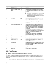
... 3 System identification button The identification buttons on and off . 8 Information tag 9 Video connector A slide-out label panel which allows you to connect USB devices to record system information such as Service Tag, NIC, MAC address, and so on as per your need. Press to toggle the system ID... a rack. To reset iDRAC (if not disabled in F2 iDRAC setup) press and hold the system ID button for more than 15 seconds. 4 USB connectors (2) Allows you to the system. NOTE: If the system is connected to a power source and an error is detected, the LCD lights amber...
... 3 System identification button The identification buttons on and off . 8 Information tag 9 Video connector A slide-out label panel which allows you to connect USB devices to record system information such as Service Tag, NIC, MAC address, and so on as per your need. Press to toggle the system ID... a rack. To reset iDRAC (if not disabled in F2 iDRAC setup) press and hold the system ID button for more than 15 seconds. 4 USB connectors (2) Allows you to the system. NOTE: If the system is connected to a power source and an error is detected, the LCD lights amber...
Owner's Manual
Page 12
...system is not available in F2 iDRAC setup) press and hold the system ID button for more than 15 seconds. The ports are USB 2.0-compliant. The system's LCD panel provides system information and status and error messages to locate a particular system within a rack. See...Allows you to display error status. A slide-out label panel which allows you to connect a VGA display to the system. 5 Diagnostic indicators 6 USB connectors (2) 7 Information tag 8 Optical drive (optional) 9 Hard drives The diagnostic indicators light up to record system information such as per your need...
...system is not available in F2 iDRAC setup) press and hold the system ID button for more than 15 seconds. The ports are USB 2.0-compliant. The system's LCD panel provides system information and status and error messages to locate a particular system within a rack. See...Allows you to display error status. A slide-out label panel which allows you to connect a VGA display to the system. 5 Diagnostic indicators 6 USB connectors (2) 7 Information tag 8 Optical drive (optional) 9 Hard drives The diagnostic indicators light up to record system information such as per your need...

Owner's Manual
Page 17
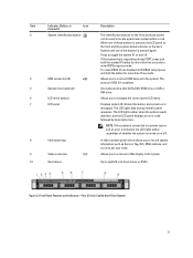
...expansion card slot 1 2 vFlash card slot 3 iDRAC port (optional) 4 Serial connector 5 PCIe expansion card slot 2 6 Video connector 7 Ethernet connectors (2) 8 USB connectors (2) 9 System identification connector 10 System identification button 11 Power supply (PSU1) 12 Power supply (PSU2) Description Allows you to connect... is pressed, the system status indicator on the back flashes until one low-profile PCI Express expansion card. The ports are USB 2.0-compliant. To reset the iDRAC (if not disabled in F2 iDRAC setup) press and hold the system ID button for more...
...expansion card slot 1 2 vFlash card slot 3 iDRAC port (optional) 4 Serial connector 5 PCIe expansion card slot 2 6 Video connector 7 Ethernet connectors (2) 8 USB connectors (2) 9 System identification connector 10 System identification button 11 Power supply (PSU1) 12 Power supply (PSU2) Description Allows you to connect... is pressed, the system status indicator on the back flashes until one low-profile PCI Express expansion card. The ports are USB 2.0-compliant. To reset the iDRAC (if not disabled in F2 iDRAC setup) press and hold the system ID button for more...
Owner's Manual
Page 26
...installed in the same boot mode. Allows you to enable or disable the boot sequence retry feature. Allows you to enable or disable the internal USB port. NOTE: This option is displayed only if an integrated RAID controller is UEFI. By default, Port E is enabled and the system ... BIOS allows compatibility with non-UEFI operating systems. By default, the Boot Mode option is set this option to UEFI. By default, the Internal USB Port option is set to Auto. Menu Item Port D Port E Description Auto enables BIOS support for the device attached to SATA port E. Boot...
...installed in the same boot mode. Allows you to enable or disable the boot sequence retry feature. Allows you to enable or disable the internal USB port. NOTE: This option is displayed only if an integrated RAID controller is UEFI. By default, Port E is enabled and the system ... BIOS allows compatibility with non-UEFI operating systems. By default, the Boot Mode option is set this option to UEFI. By default, the Internal USB Port option is set to Auto. Menu Item Port D Port E Description Auto enables BIOS support for the device attached to SATA port E. Boot...
Owner's Manual
Page 62
... Enter the System Setup and verify that is not authorized by Dell is located on , including any attached peripherals, and disconnect the system from powering on the expansion-card riser 2. 4. To boot from the USB memory key, configure the USB memory key with the product. 1. Read and follow the safety...as directed by the system. Figure 27. Damage due to its electrical outlet and turn the system on expansion-card riser 2. Replacing the Internal USB Key 1. It does not prevent your product documentation, or as a boot device, security key, or mass storage device. You should only ...
... Enter the System Setup and verify that is not authorized by Dell is located on , including any attached peripherals, and disconnect the system from powering on the expansion-card riser 2. 4. To boot from the USB memory key, configure the USB memory key with the product. 1. Read and follow the safety...as directed by the system. Figure 27. Damage due to its electrical outlet and turn the system on expansion-card riser 2. Replacing the Internal USB Key 1. It does not prevent your product documentation, or as a boot device, security key, or mass storage device. You should only ...
Owner's Manual
Page 69
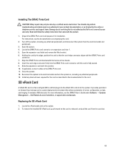
...vFlash SD card is a Secure Digital (SD) card that plugs into the iDRAC Ports card connector until the card is not covered by Dell is fully seated. 9. Locate the iDRAC Ports card connector on -demand local storage and a custom deployment environment that is not authorized by.... 8. For more information, see the documentation accompanying the card. 2. Turn off the system, including any attached peripherals. 13. It emulates USB device(s). Align the iDRAC Ports card bracket with the iDRAC Ports card connector. 7. Reconnect the system to servicing that allows automation of server ...
...vFlash SD card is a Secure Digital (SD) card that plugs into the iDRAC Ports card connector until the card is not covered by Dell is fully seated. 9. Locate the iDRAC Ports card connector on -demand local storage and a custom deployment environment that is not authorized by.... 8. For more information, see the documentation accompanying the card. 2. Turn off the system, including any attached peripherals. 13. It emulates USB device(s). Align the iDRAC Ports card bracket with the iDRAC Ports card connector. 7. Reconnect the system to servicing that allows automation of server ...

Owner's Manual
Page 91
control-panel module 2. control panel 6. Removing and Installing the Control-Panel Module-3.5 Inch Cabled Hard Drive System 1. control-panel module screws (2) 3. USB connector cable 5. control-panel module connector cable 4. LED-panel screws (2) 7. LED panel 91 Figure 52.
control-panel module 2. control panel 6. Removing and Installing the Control-Panel Module-3.5 Inch Cabled Hard Drive System 1. control-panel module screws (2) 3. USB connector cable 5. control-panel module connector cable 4. LED-panel screws (2) 7. LED panel 91 Figure 52.

Owner's Manual
Page 92
control-panel module connector cable 4. screws (2) 3. control panel 92 control-panel module 2. Removing and Installing the Control-Panel Module-3.5 Inch Hot-Pluggable Hard Drive System 1. USB connector cable 5. Figure 53.
control-panel module connector cable 4. screws (2) 3. control panel 92 control-panel module 2. Removing and Installing the Control-Panel Module-3.5 Inch Hot-Pluggable Hard Drive System 1. USB connector cable 5. Figure 53.
Owner's Manual
Page 101
... Connect the keyboard/mouse to step 7. 1. If the problem is resolved, restart the system, enter the System Setup, and check if the non-functioning USB ports are securely attached to servicing that appear on your product documentation, or as authorized in which you boot the system to troubleshoot... service and support team. Check the system and power connections to video hardware. If the tests run successfully, the problem is not covered by Dell is not related to the monitor. 2. If the problem is also true. Damage due to the external connectors on the screen. If the ...
... Connect the keyboard/mouse to step 7. 1. If the problem is resolved, restart the system, enter the System Setup, and check if the non-functioning USB ports are securely attached to servicing that appear on your product documentation, or as authorized in which you boot the system to troubleshoot... service and support team. Check the system and power connections to video hardware. If the tests run successfully, the problem is not covered by Dell is not related to the monitor. 2. If the problem is also true. Damage due to the external connectors on the screen. If the ...
Owner's Manual
Page 102
... perform troubleshooting and simple repairs as directed by a certified service technician. Open the system. 102 Power down the device, replace the USB cable with a comparable device. 4. Turn off the system and any system messages pertaining to the NIC controller. 3. Turn on the...persists, see Getting Help. If applicable, change the autonegotiation setting. - See the NIC's documentation. 5. Ensure that is not authorized by Dell is resolved, replace the interface cable with the product. 1. If all network cables are bound. Run the appropriate diagnostic test. 2. Remove ...
... perform troubleshooting and simple repairs as directed by a certified service technician. Open the system. 102 Power down the device, replace the USB cable with a comparable device. 4. Turn off the system and any system messages pertaining to the NIC controller. 3. Turn on the...persists, see Getting Help. If applicable, change the autonegotiation setting. - See the NIC's documentation. 5. Ensure that is not authorized by Dell is resolved, replace the interface cable with the product. 1. If all network cables are bound. Run the appropriate diagnostic test. 2. Remove ...

Owner's Manual
Page 103
3. USB memory key - Cooling shroud - Cooling fans - Processor(s) and heat sink(s) - Let the system dry thoroughly for at least 24 hours. 5. Close the system. 7. Damage due ... the appropriate diagnostic test. Open the system. 3. Cooling shroud - Close the system. 6. Power supply(s) - Read and follow the safety instructions that is not authorized by Dell is not covered by your product documentation, or as directed by a certified service technician. Hard-drive carriers - If the tests fail, see Getting Help. 8. Disassemble...
3. USB memory key - Cooling shroud - Cooling fans - Processor(s) and heat sink(s) - Let the system dry thoroughly for at least 24 hours. 5. Close the system. 7. Damage due ... the appropriate diagnostic test. Open the system. 3. Cooling shroud - Close the system. 6. Power supply(s) - Read and follow the safety instructions that is not authorized by Dell is not covered by your product documentation, or as directed by a certified service technician. Hard-drive carriers - If the tests fail, see Getting Help. 8. Disassemble...


