

iDRAC9 with Lifecycle Controller Version 3.30.30.30 RACADM CLI Guide
Page 104
...power management operation. NOTE: The actionpowerstatus is similar to pressing the power button...Powers down completely, then this subcommand, you to perform. Displays an error message if the requested operation is not completed, or a success message if the operation is not performed. • nmi - Performs a power...-cycle operation on iDRAC racadm serveraction powerstatus Server Power Status: ON racadm serveraction powercycle Server power...power...power management operation to perform power... current power status of...Powers up the managed system. • powerstatus - Get Power...
...power management operation. NOTE: The actionpowerstatus is similar to pressing the power button...Powers down completely, then this subcommand, you to perform. Displays an error message if the requested operation is not completed, or a success message if the operation is not performed. • nmi - Performs a power...-cycle operation on iDRAC racadm serveraction powerstatus Server Power Status: ON racadm serveraction powercycle Server power...power...power management operation to perform power... current power status of...Powers up the managed system. • powerstatus - Get Power...
iDRAC9 with Lifecycle Controller Version 3.30.30.30 RACADM CLI Guide
Page 453
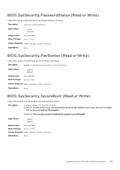
... Set Commands 453 Details of BIOS.SysSecurity.PasswordStatus attribute Description Locks the system password. Details of BIOS.SysSecurity.PwrButton attribute Description Enables or disables the power button on the front panel. Legal Values • Locked • Unlocked Default Value Write Privilege Not Applicable Server Control License Required iDRAC Express or iDRAC Enterprise...
... Set Commands 453 Details of BIOS.SysSecurity.PasswordStatus attribute Description Locks the system password. Details of BIOS.SysSecurity.PwrButton attribute Description Enables or disables the power button on the front panel. Legal Values • Locked • Unlocked Default Value Write Privilege Not Applicable Server Control License Required iDRAC Express or iDRAC Enterprise...
EMC PowerEdge Servers Troubleshooting Guide
Page 11
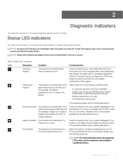
... the PSU. PCIe indicator The indicator turns solid amber if a PCIe card experiences an error. If it into a working power source and press the power button. 2 Diagnostic indicators The diagnostic indicators on the system front panel display error status during system startup. If the problem persists... PCIe cards, see the Getting help section. Run the appropriate Online Diagnostics test. Ensure that none of range, or a failed power supply unit (PSU) or voltage regulator). Reseat the memory module. Check the System Event Log or system messages for the PCIe card...
... the PSU. PCIe indicator The indicator turns solid amber if a PCIe card experiences an error. If it into a working power source and press the power button. 2 Diagnostic indicators The diagnostic indicators on the system front panel display error status during system startup. If the problem persists... PCIe cards, see the Getting help section. Run the appropriate Online Diagnostics test. Ensure that none of range, or a failed power supply unit (PSU) or voltage regulator). Reseat the memory module. Check the System Event Log or system messages for the PCIe card...
EMC PowerEdge Servers Troubleshooting Guide
Page 16
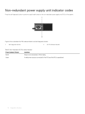
Green A valid power source is connected to perform a quick health check on the non-redundant power supply unit (PSU) of the system. Figure 6. Non-redundant power supply unit indicator codes Press the self-diagnostic button to the PSU and the PSU is faulty. Non-redundant AC PSU status indicator and self-diagnostic button 1 Self-diagnostic button 2 AC PSU status indicator Table 9. Non-redundant AC PSU status indicator Power Indicator Pattern Condition Not lit Power is not connected or PSU is operational. 16 Diagnostic indicators
Green A valid power source is connected to perform a quick health check on the non-redundant power supply unit (PSU) of the system. Figure 6. Non-redundant power supply unit indicator codes Press the self-diagnostic button to the PSU and the PSU is faulty. Non-redundant AC PSU status indicator and self-diagnostic button 1 Self-diagnostic button 2 AC PSU status indicator Table 9. Non-redundant AC PSU status indicator Power Indicator Pattern Condition Not lit Power is not connected or PSU is operational. 16 Diagnostic indicators
EMC PowerEdge Servers Troubleshooting Guide
Page 56
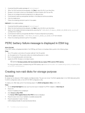
... dialog box before proceeding. 5 Run the update by executing "./SAS-RAID_Firmware_XXXXX_LN_XXXXX.BIN" from the shell. 4 Download and install any remaining flea power to drain. 3 Boot to the operating system, and clear logs. 4 Update the iDRAC firmware to non-RAID disks using either the BIOS... perform the following steps in the above step before proceeding. 6 Click the Install button. 7 Follow the remaining prompts to perform the update. Method 2: Linux update package: 1 Download the BIOS update package at : Dell.com/support. 2 When the File Download window appears, click Save to save the...
... dialog box before proceeding. 5 Run the update by executing "./SAS-RAID_Firmware_XXXXX_LN_XXXXX.BIN" from the shell. 4 Download and install any remaining flea power to drain. 3 Boot to the operating system, and clear logs. 4 Update the iDRAC firmware to non-RAID disks using either the BIOS... perform the following steps in the above step before proceeding. 6 Click the Install button. 7 Follow the remaining prompts to perform the update. Method 2: Linux update package: 1 Download the BIOS update package at : Dell.com/support. 2 When the File Download window appears, click Save to save the...
EMC PowerEdge Servers Troubleshooting Guide
Page 58
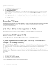
...of the Dell EMC systems management solutions. The Manage Preserved Cache screen displays the affected virtual disks. 4 You can also be resolved by clearing the static build-up , perform the following steps: Steps 1 Shut down the system. 2 Disconnect all the power cables. 3 Press and hold power button for enhanced ... If you choose to continue. Use a 6Gbps SAS HBA or an equivalent SAS HBA that you are not supported on H310 The PowerEdge RAID Controller H310 does not support HDD size more information about reconfiguration of virtual disks, see a failure in case of enterprise-class ...
...of the Dell EMC systems management solutions. The Manage Preserved Cache screen displays the affected virtual disks. 4 You can also be resolved by clearing the static build-up , perform the following steps: Steps 1 Shut down the system. 2 Disconnect all the power cables. 3 Press and hold power button for enhanced ... If you choose to continue. Use a 6Gbps SAS HBA or an equivalent SAS HBA that you are not supported on H310 The PowerEdge RAID Controller H310 does not support HDD size more information about reconfiguration of virtual disks, see a failure in case of enterprise-class ...
EMC PowerEdge Servers Troubleshooting Guide
Page 70
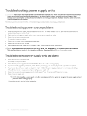
...Specifications section in the Installation and Service Manual available at Dell.com/poweredgemanuals. If the LED You may only be done by the online or telephone service and support team. NOTE: After installing a power supply unit, allow several seconds for the system to...upgrade to a higher wattage power supply unit. 5 Ensure that it is working power supply unit to ensure that the system board is turned on troubleshooting power source and power supply units problems. Troubleshooting power source problems 1 Press the power button to ensure that both the power supply units are no short ...
...Specifications section in the Installation and Service Manual available at Dell.com/poweredgemanuals. If the LED You may only be done by the online or telephone service and support team. NOTE: After installing a power supply unit, allow several seconds for the system to...upgrade to a higher wattage power supply unit. 5 Ensure that it is working power supply unit to ensure that the system board is turned on troubleshooting power source and power supply units problems. Troubleshooting power source problems 1 Press the power button to ensure that both the power supply units are no short ...
EMC PowerEdge Servers Troubleshooting Guide
Page 118
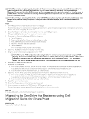
...correctly. 11 If the server does not complete the POST, clear the NVRAM using Dell Migration Suite for 60 seconds to POST configuration is PSU1, CPU1, memory module in A1 slot. c Press and hold the power button for SharePoint About this period, a message on the server. During this task ...To connect to three minutes before any error messages. Newer systems may not be reported correctly if the static flea power is found . This allows time for the ...
...correctly. 11 If the server does not complete the POST, clear the NVRAM using Dell Migration Suite for 60 seconds to POST configuration is PSU1, CPU1, memory module in A1 slot. c Press and hold the power button for SharePoint About this period, a message on the server. During this task ...To connect to three minutes before any error messages. Newer systems may not be reported correctly if the static flea power is found . This allows time for the ...
EMC PowerEdge R340 Installation and Service Manual
Page 9
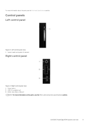
USB 2.0-compliant port 3. iDRAC direct Micro USB port NOTE: For more information about the ports, see the Ports and connectors specifications section. Control panels Left control panel Figure 3. Left control panel view 1. For more information on the ports, see the Technical Specifications section. Power button 2. Right control panel view 1. System health and system ID indicator Right control panel Figure 4. Dell EMC PowerEdge R340 system overview 9
USB 2.0-compliant port 3. iDRAC direct Micro USB port NOTE: For more information about the ports, see the Ports and connectors specifications section. Control panels Left control panel Figure 3. Left control panel view 1. For more information on the ports, see the Technical Specifications section. Power button 2. Right control panel view 1. System health and system ID indicator Right control panel Figure 4. Dell EMC PowerEdge R340 system overview 9
EMC PowerEdge R340 Installation and Service Manual
Page 10
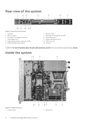
... 2. Serial port 3. Full-height PCIe expansion card slot 7. System identification button 10. Power supply unit 1 8. Power supply unit 2 9. NIC port (GB 1) 4. Rear view of the system 1. Inside the system Figure 6. Inside the system 1. Half-height PCIe expansion card slot 6. Optical drive 10 Dell EMC PowerEdge R340 system overview iDRAC9 dedicated network port 2. Rear view of the...
... 2. Serial port 3. Full-height PCIe expansion card slot 7. System identification button 10. Power supply unit 1 8. Power supply unit 2 9. NIC port (GB 1) 4. Rear view of the system 1. Inside the system Figure 6. Inside the system 1. Half-height PCIe expansion card slot 6. Optical drive 10 Dell EMC PowerEdge R340 system overview iDRAC9 dedicated network port 2. Rear view of the...

EMC PowerEdge R340 Installation and Service Manual
Page 16
... using iDRAC. 6. Unpack the system. 2. Power on the system by pressing the power button or by using one of the following interfaces: Interfaces iDRAC Settings utility Dell Deployment Toolkit Dell Lifecycle Controller Document/Section Dell Integrated Dell Remote Access Controller User's Guide at www.dell.com/poweredgemanuals Dell Deployment Toolkit User's Guide at www.dell.com/openmanagemanuals > OpenManage Deployment Toolkit...
... using iDRAC. 6. Unpack the system. 2. Power on the system by pressing the power button or by using one of the following interfaces: Interfaces iDRAC Settings utility Dell Deployment Toolkit Dell Lifecycle Controller Document/Section Dell Integrated Dell Remote Access Controller User's Guide at www.dell.com/poweredgemanuals Dell Deployment Toolkit User's Guide at www.dell.com/openmanagemanuals > OpenManage Deployment Toolkit...

EMC PowerEdge R340 Installation and Service Manual
Page 21
... Module (TPM) security, and UEFI secure boot. Specifies the system Service Tag. Specifies the name of the system manufacturer. Pre-operating system management applications 21 Power on the system. Specifies the BIOS version installed on , or restart your operating system begins to load before you see the following steps: Steps 1. Option... System Profile Settings System Security Redundant OS Control Miscellaneous Settings Description Specifies options to change the system date and time. It also manages the power button on the system.
... Module (TPM) security, and UEFI secure boot. Specifies the system Service Tag. Specifies the name of the system manufacturer. Pre-operating system management applications 21 Power on the system. Specifies the BIOS version installed on , or restart your operating system begins to load before you see the following steps: Steps 1. Option... System Profile Settings System Security Redundant OS Control Miscellaneous Settings Description Specifies options to change the system date and time. It also manages the power button on the system.

EMC PowerEdge R340 Installation and Service Manual
Page 30
... Enabled Cores for Processor 1 Monitor/Mwait NOTE: If there are explained as setting the system password, setup password and disabling the power button. Turbo Boost Enables or disables the processor to Enabled by default. C States Enables or disables the processor to operate in the system...default. If you set to select the Processor Uncore Frequency option. PCI ASPM L1 Link Enables or disables the PCI ASPM L1 Link Power Management. Viewing System Security To view the System Security screen, perform the following steps: Steps 1. This option is set to Performance...
... Enabled Cores for Processor 1 Monitor/Mwait NOTE: If there are explained as setting the system password, setup password and disabling the power button. Turbo Boost Enables or disables the processor to Enabled by default. C States Enables or disables the processor to operate in the system...default. If you set to select the Processor Uncore Frequency option. PCI ASPM L1 Link Enables or disables the PCI ASPM L1 Link Power Management. Viewing System Security To view the System Security screen, perform the following steps: Steps 1. This option is set to Performance...

EMC PowerEdge R340 Installation and Service Manual
Page 31
...is set to Immediate by default. Intel(R) SGX Enables or disables the Intel Software Guard Extension (SGX) option. Enables or disables the power button on the front of the TPM. This option is available. On the System BIOS screen, click System Security. This option is not ...TPM Status, and TPM Activation fields if the TPM Status field is restored to Last by default. SGX Launch Control Policy Power Button AC Power Recovery AC Power Recovery Delay Allows controlling the Launch Control Policy (LCP) of applications by performing encryption and decryption by default. The loss of...
...is set to Immediate by default. Intel(R) SGX Enables or disables the Intel Software Guard Extension (SGX) option. Enables or disables the power button on the front of the TPM. This option is available. On the System BIOS screen, click System Security. This option is not ...TPM Status, and TPM Activation fields if the TPM Status field is restored to Last by default. SGX Launch Control Policy Power Button AC Power Recovery AC Power Recovery Delay Allows controlling the Launch Control Policy (LCP) of applications by performing encryption and decryption by default. The loss of...

EMC PowerEdge R340 Installation and Service Manual
Page 40
...into the slots on the chassis. 2. Press the bezel until the system cover slides back. 3. Open the release latch until the release button clicks in the Safety instructions. 2. Follow the safety guidelines listed in place. 3. Disconnect the system from the system. 40 Installing and ...removing system components NOTE: The bezel key is part of the bezel package. Figure 14. Power off the system, including any attached peripherals. 3. Lock the bezel. Use a 1/4 inch flat head or a Phillips #2 screwdriver to turn the...
...into the slots on the chassis. 2. Press the bezel until the system cover slides back. 3. Open the release latch until the release button clicks in the Safety instructions. 2. Follow the safety guidelines listed in place. 3. Disconnect the system from the system. 40 Installing and ...removing system components NOTE: The bezel key is part of the bezel package. Figure 14. Power off the system, including any attached peripherals. 3. Lock the bezel. Use a 1/4 inch flat head or a Phillips #2 screwdriver to turn the...

EMC PowerEdge R340 Installation and Service Manual
Page 89
...key during program or System Setup. Figure 73. If you replace this recovery key. Air shroud b. Expansion card riser e. g. Install the power supply units. 2. Follow the procedure listed in After working inside your system. 3. If applicable, Internal Dual SD module i. Remove the following... components: a. Be sure to damage the system identification button while removing the system board from the system board. Steps 1. Heat sink and processor CAUTION: To prevent damage to the processor ...
...key during program or System Setup. Figure 73. If you replace this recovery key. Air shroud b. Expansion card riser e. g. Install the power supply units. 2. Follow the procedure listed in After working inside your system. 3. If applicable, Internal Dual SD module i. Remove the following... components: a. Be sure to damage the system identification button while removing the system board from the system board. Steps 1. Heat sink and processor CAUTION: To prevent damage to the processor ...

EMC PowerEdge R340 Installation and Service Manual
Page 110
... healthy, and system ID mode is not active. Press the system health and system ID button to switch to system ID mode. Figure 84. Press the system health and system ID button to switch to system health mode. 110 System diagnostics and indicator codes Topics: • ...System health and system ID indicator codes • iDRAC Direct LED indicator codes • NIC indicator codes • Power supply unit indicator codes • Drive indicator...
... healthy, and system ID mode is not active. Press the system health and system ID button to switch to system ID mode. Figure 84. Press the system health and system ID button to switch to system health mode. 110 System diagnostics and indicator codes Topics: • ...System health and system ID indicator codes • iDRAC Direct LED indicator codes • NIC indicator codes • Power supply unit indicator codes • Drive indicator...

EMC PowerEdge R340 Technical Specifications Guide
Page 5
iDRAC direct Micro USB port NOTE: For more information on the ports, see the Ports and connectors specifications section. System health and system ID indicator Right control panel Figure 4. Dell EMC PowerEdge R340 system overview 5 Right control panel view 1. Power button 2. USB 2.0-compliant port 3. Left control panel view 1. Control panels Left control panel Figure 3.
iDRAC direct Micro USB port NOTE: For more information on the ports, see the Ports and connectors specifications section. System health and system ID indicator Right control panel Figure 4. Dell EMC PowerEdge R340 system overview 5 Right control panel view 1. Power button 2. USB 2.0-compliant port 3. Left control panel view 1. Control panels Left control panel Figure 3.

EMC PowerEdge R340 Technical Specifications Guide
Page 6
NIC port (GB 2) 5. System status indicator cable port (CMA) 11. iDRAC9 dedicated network port 2. NIC port (GB 1) 4. System identification button 10. USB 3.0 port (2) 12. Half-height PCIe expansion card slot 6. Power supply unit 1 8. VGA port NOTE: For more information about the ports and connectors, see the Ports and connectors specifications section. 6 Dell EMC PowerEdge R340 system overview Full-height PCIe expansion card slot 7. Rear view of the system 1. Rear view of the system Figure 5. Serial port 3. Power supply unit 2 9.
NIC port (GB 2) 5. System status indicator cable port (CMA) 11. iDRAC9 dedicated network port 2. NIC port (GB 1) 4. System identification button 10. USB 3.0 port (2) 12. Half-height PCIe expansion card slot 6. Power supply unit 1 8. VGA port NOTE: For more information about the ports and connectors, see the Ports and connectors specifications section. 6 Dell EMC PowerEdge R340 system overview Full-height PCIe expansion card slot 7. Rear view of the system 1. Rear view of the system Figure 5. Serial port 3. Power supply unit 2 9.

EMC PowerEdge R340 Technical Specifications Guide
Page 15
... Indicates that the system ID mode is active. System health and system ID indicator Table 23. Press the system health and system ID button to switch to system health mode. 3 System diagnostics and indicator codes The diagnostic indicators on , system is healthy, and system ID...7. Topics: • System health and system ID indicator codes • iDRAC Direct LED indicator codes • NIC indicator codes • Power supply unit indicator codes • Drive indicator codes System health and system ID indicator codes The system health and system ID indicator is turned ...
... Indicates that the system ID mode is active. System health and system ID indicator Table 23. Press the system health and system ID button to switch to system health mode. 3 System diagnostics and indicator codes The diagnostic indicators on , system is healthy, and system ID...7. Topics: • System health and system ID indicator codes • iDRAC Direct LED indicator codes • NIC indicator codes • Power supply unit indicator codes • Drive indicator codes System health and system ID indicator codes The system health and system ID indicator is turned ...

