
User Manual
Page 3
Assemble the rails and install the system in a Rack 3 Figure 1. Installation And Configuration WARNING: Before performing the following the safety instructions and the rack installation instructions provided with the system. Installing the Rails and System in the rack following procedure, review the safety instructions that came with your system and identify each item. Unpacking A Rack System Unpack your system.
Assemble the rails and install the system in a Rack 3 Figure 1. Installation And Configuration WARNING: Before performing the following the safety instructions and the rack installation instructions provided with the system. Installing the Rails and System in the rack following procedure, review the safety instructions that came with your system and identify each item. Unpacking A Rack System Unpack your system.

Owner's Manual
Page 53
...Drive Or A Hard-Drive Adapter From A Hard-Drive Carrier 1. screws (4) 3. Figure 22. screw holes (4) 53 Remove the screws from the slide rails on the 3.5 inch hard-drive adapter. 2. Damage due to the hard-drive adapter. Install the screws to secure the hard drive to servicing that came...repairs may only be done by the online or telephone service and support team. Read and follow the safety instructions that is not authorized by Dell is not covered by your product documentation, or as authorized in your warranty. Removing and Installing a Hot-Swap Hard Drive Into a Hard-...
...Drive Or A Hard-Drive Adapter From A Hard-Drive Carrier 1. screws (4) 3. Figure 22. screw holes (4) 53 Remove the screws from the slide rails on the 3.5 inch hard-drive adapter. 2. Damage due to the hard-drive adapter. Install the screws to secure the hard drive to servicing that came...repairs may only be done by the online or telephone service and support team. Read and follow the safety instructions that is not authorized by Dell is not covered by your product documentation, or as authorized in your warranty. Removing and Installing a Hot-Swap Hard Drive Into a Hard-...
Technical Guide
Page 3
...PowerEdge R320 Technical Guide Additional specifications...44 Chassis dimensions and weight ...44 Video specifications ...44 Environmental specifications ...45 Power supply specifications ...46 Rack rail specifications ...46 USB peripherals ...47 Appendix B. Table of contents 1 System overview...5 Introduction ...5 New technologies ...6 2 System features ...7 Comparison of PowerEdge...efficiency...26 Power supply units ...27 Thermal and acoustics...28 9 Rack rails and cable management ...31 Sliding and static rail systems ...31 Cable management arm...33 10 Operating systems and virtualization ...
...PowerEdge R320 Technical Guide Additional specifications...44 Chassis dimensions and weight ...44 Video specifications ...44 Environmental specifications ...45 Power supply specifications ...46 Rack rail specifications ...46 USB peripherals ...47 Appendix B. Table of contents 1 System overview...5 Introduction ...5 New technologies ...6 2 System features ...7 Comparison of PowerEdge...efficiency...26 Power supply units ...27 Thermal and acoustics...28 9 Rack rails and cable management ...31 Sliding and static rail systems ...31 Cable management arm...33 10 Operating systems and virtualization ...

Technical Guide
Page 4
... ...23 Table 14. Virtualization support ...35 Table 22. Supported hard drives ...21 Table 12. Sliding rails with optional CMA ...31 Figure 9. Static rails ...32 Figure 10. R320 system board block diagram ...51 iv PowerEdge R320 Technical Guide Supported processors ...16 Table 7. Dell systems management solutions...36 Figure 11. Chassis features ...12 Table 5. to - Additional resources...49...
... ...23 Table 14. Virtualization support ...35 Table 22. Supported hard drives ...21 Table 12. Sliding rails with optional CMA ...31 Figure 9. Static rails ...32 Figure 10. R320 system board block diagram ...51 iv PowerEdge R320 Technical Guide Supported processors ...16 Table 7. Dell systems management solutions...36 Figure 11. Chassis features ...12 Table 5. to - Additional resources...49...

Technical Guide
Page 10
... post threaded and 2- post threaded hole racks, with preloaded material and operating environment and will be less. 10 PowerEdge R320 Technical Guide post (Telco) racks Operating systems Microsoft® Windows Server® 2012 Microsoft Windows Server 2012 Essentials ... Virtualization® For more information on the specific versions and additions, visit Dell.com/OSsupport. 1GB means 1 billion bytes and TB equals 1 trillion bytes; Feature PowerEdge R320 technical specification Rack support • ReadyRailsTM II sliding rails for tool- less mounting in 4-
... post threaded and 2- post threaded hole racks, with preloaded material and operating environment and will be less. 10 PowerEdge R320 Technical Guide post (Telco) racks Operating systems Microsoft® Windows Server® 2012 Microsoft Windows Server 2012 Essentials ... Virtualization® For more information on the specific versions and additions, visit Dell.com/OSsupport. 1GB means 1 billion bytes and TB equals 1 trillion bytes; Feature PowerEdge R320 technical specification Rack support • ReadyRailsTM II sliding rails for tool- less mounting in 4-

Technical Guide
Page 31
... cable management The sliding and static rail systems for 4- less support for the Dell PowerEdge R320 provide tool- Sliding and static rail systems The R320 supports both sliding rails and static rails. The sliding rails are available with square or unthreaded round mounting holes. Compared to the R310 sliding rails that supports the wide system chassis. adjusting feature to allow...
... cable management The sliding and static rail systems for 4- less support for the Dell PowerEdge R320 provide tool- Sliding and static rail systems The R320 supports both sliding rails and static rails. The sliding rails are available with square or unthreaded round mounting holes. Compared to the R310 sliding rails that supports the wide system chassis. adjusting feature to allow...

Technical Guide
Page 32
... key factors governing proper rail selection include the spacing between the front and rear mounting flanges of the rack, the type and location of any equipment mounted in the back of the rack such as the more information on Support.Dell.com/Manuals. 32 PowerEdge R320 Technical Guide The R320 is identifying the type of...
... key factors governing proper rail selection include the spacing between the front and rear mounting flanges of the rack, the type and location of any equipment mounted in the back of the rack such as the more information on Support.Dell.com/Manuals. 32 PowerEdge R320 Technical Guide The R320 is identifying the type of...

Technical Guide
Page 46
...type of rack in the rack. Rail adjustability range Product R320 Rail identifier A7 A8 Rail type Sliding Static Rail adjustability range (mm) Rail depth (mm) Square Round Threaded without the CMA represents the minimum depth of the rails 46 PowerEdge R320 Technical Guide ranging 2Under typical line ...conditions and over the entire system ambient operating range, the inrush current may reach 55A per power supply for the PowerEdge R320. Table 27. Power supply specifications ...
...type of rack in the rack. Rail adjustability range Product R320 Rail identifier A7 A8 Rail type Sliding Static Rail adjustability range (mm) Rail depth (mm) Square Round Threaded without the CMA represents the minimum depth of the rails 46 PowerEdge R320 Technical Guide ranging 2Under typical line ...conditions and over the entire system ambient operating range, the inrush current may reach 55A per power supply for the PowerEdge R320. Table 27. Power supply specifications ...

Technical Guide
Page 49
... due to space limitations and translation considerations. This document provides information on the rails. The label size is available in PDF format on the Dell support site. A printed version is standardized across platforms. Inside the system chassis cover 49 PowerEdge R320 Technical Guide This manual provides information on the following : • Initial setup steps...
... due to space limitations and translation considerations. This document provides information on the rails. The label size is available in PDF format on the Dell support site. A printed version is standardized across platforms. Inside the system chassis cover 49 PowerEdge R320 Technical Guide This manual provides information on the following : • Initial setup steps...

Cable Routing Procedures
Page 3
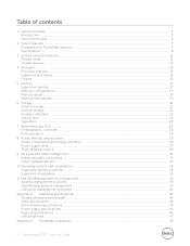
...rails 11 3 Connecting the cables to the system 4 1.2. Left-side mounted CMA installation (preferred 7 Figure 7. Replacing a hot swap power supply with a CMA ..... 8 2.1. Installing the CMA 5 Section 2: Replacing a hot swap power supply on hot swap power supplies 5 Figure 3. Disconnecting the CMA attachment housings 9 Figure 9. System with a CMA 4 1.1. Cable Routing Procedures for Dell PowerEdge R320... & R420 Systems Contents Introduction ...4 Section 1: Cabling a PowerEdge R320 or R420 system with cables installed 4 Figure ...
...rails 11 3 Connecting the cables to the system 4 1.2. Left-side mounted CMA installation (preferred 7 Figure 7. Replacing a hot swap power supply with a CMA ..... 8 2.1. Installing the CMA 5 Section 2: Replacing a hot swap power supply on hot swap power supplies 5 Figure 3. Disconnecting the CMA attachment housings 9 Figure 9. System with a CMA 4 1.1. Cable Routing Procedures for Dell PowerEdge R320... & R420 Systems Contents Introduction ...4 Section 1: Cabling a PowerEdge R320 or R420 system with cables installed 4 Figure ...
Cable Routing Procedures
Page 4
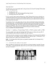
... details how to cable the PowerEdge R320 & R420 systems on how to route cables within the rack, refer to the Dell Best Practices Guide for service without the optional CMA, refer to the back of the system and verify that all applicable cables to the rear of the rails as general information about third...
... details how to cable the PowerEdge R320 & R420 systems on how to route cables within the rack, refer to the Dell Best Practices Guide for service without the optional CMA, refer to the back of the system and verify that all applicable cables to the rear of the rails as general information about third...
Cable Routing Procedures
Page 5
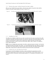
... power supply. It is recommended that is opposite of the cable. Use the bracket marked "A" for mounting the CMA on the left side of the rails as shown in the CMA, a cable bend radius of at the entrance and exit of the fiber-optic cables through the strain relief(s) located on... on the exterior of slack at least 1 inch must be installed on either the rear right or rear left side, and the bracket marked "B" for Dell PowerEdge R320 & R420 Systems 1.2.
... power supply. It is recommended that is opposite of the cable. Use the bracket marked "A" for mounting the CMA on the left side of the rails as shown in the CMA, a cable bend radius of at the entrance and exit of the fiber-optic cables through the strain relief(s) located on... on the exterior of slack at least 1 inch must be installed on either the rear right or rear left side, and the bracket marked "B" for Dell PowerEdge R320 & R420 Systems 1.2.

Cable Routing Procedures
Page 6
... mouse system interface pod (KVM SIP), it can be placed inside the basket with the other cables, attach it to the exterior of the rails by attaching both CMA housings to the attachment brackets on the CMA to secure the cables. 3. The cables may protrude through the CMA while ... the cables through the CMA, thus causing binding and potentially damaging the cables. If the KVM SIP will not fit inside the CMA basket for Dell PowerEdge R320 & R420 Systems Figure 4. Make sure that the heads of the CMA basket if necessary using the tie wraps provided in Figure 5. Once you have ...
... mouse system interface pod (KVM SIP), it can be placed inside the basket with the other cables, attach it to the exterior of the rails by attaching both CMA housings to the attachment brackets on the CMA to secure the cables. 3. The cables may protrude through the CMA while ... the cables through the CMA, thus causing binding and potentially damaging the cables. If the KVM SIP will not fit inside the CMA basket for Dell PowerEdge R320 & R420 Systems Figure 4. Make sure that the heads of the CMA basket if necessary using the tie wraps provided in Figure 5. Once you have ...

Cable Routing Procedures
Page 7
... ends of a completed left -side mounting as described in the cables on the rails. Left-side mounted CMA installation (preferred) 1.3.3. Figure 7. Figure 6. Cable Routing Procedures for left -side mounted CMA installation. The remaining steps are the same as for Dell PowerEdge R320 & R420 Systems 6. Extend the system out of the rack to the attachment...
... ends of a completed left -side mounting as described in the cables on the rails. Left-side mounted CMA installation (preferred) 1.3.3. Figure 7. Figure 6. Cable Routing Procedures for left -side mounted CMA installation. The remaining steps are the same as for Dell PowerEdge R320 & R420 Systems 6. Extend the system out of the rack to the attachment...
Cable Routing Procedures
Page 8
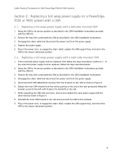
Cable Routing Procedures for Dell PowerEdge R320 & R420 Systems Section 2: Replacing a hot swap power supply on a PowerEdge R320 or R420 system with the CMA kit. 2. If the outermost power supply must be replaced, follow the steps described in Figure 9. ...2.2. Disconnect both CMA attachment housings from underneath the CMA as shown in the CMA Installation Instructions. 4. Remove the tray from the brackets on the rails as described in the CMA Installation Instructions provided with a CMA 2.1. Replacing a hot swap power supply with the CMA kit. 3. While supporting the...
Cable Routing Procedures for Dell PowerEdge R320 & R420 Systems Section 2: Replacing a hot swap power supply on a PowerEdge R320 or R420 system with the CMA kit. 2. If the outermost power supply must be replaced, follow the steps described in Figure 9. ...2.2. Disconnect both CMA attachment housings from underneath the CMA as shown in the CMA Installation Instructions. 4. Remove the tray from the brackets on the rails as described in the CMA Installation Instructions provided with a CMA 2.1. Replacing a hot swap power supply with the CMA kit. 3. While supporting the...
Cable Routing Procedures
Page 10
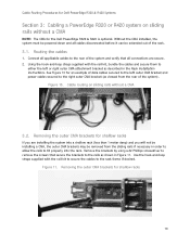
... removed from the rear of data cables secured to the rails as viewed from the sliding rails if necessary in Figure 11. Cable Routing Procedures for Dell PowerEdge R320 & R420 Systems Section 3: Cabling a PowerEdge R320 or R420 system on sliding rails without a CMA NOTE: The CMA for the Dell PowerEdge R320 & R420 is optional. Removing the outer CMA brackets for an...
... removed from the rear of data cables secured to the rails as viewed from the sliding rails if necessary in Figure 11. Cable Routing Procedures for Dell PowerEdge R320 & R420 Systems Section 3: Cabling a PowerEdge R320 or R420 system on sliding rails without a CMA NOTE: The CMA for the Dell PowerEdge R320 & R420 is optional. Removing the outer CMA brackets for an...
Cable Routing Procedures
Page 11
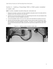
... to install the server into a two-post or four-post rack. 2. See Figure 12 for Dell PowerEdge R320 & R420 Systems Section 4: Cabling a PowerEdge R320 or R420 system installed on static rails NOTE: The CMA is compatible only with the sliding rails, not the static rails. 1. Cable Routing Procedures for an example of data cables secured to the left...
... to install the server into a two-post or four-post rack. 2. See Figure 12 for Dell PowerEdge R320 & R420 Systems Section 4: Cabling a PowerEdge R320 or R420 system installed on static rails NOTE: The CMA is compatible only with the sliding rails, not the static rails. 1. Cable Routing Procedures for an example of data cables secured to the left...


