
Glossary
Page 2
... and correction. Electromagnetic interference. coprocessor - device driver - DHCP - See device driver. The part of specific processing tasks. A math coprocessor, for peripherals, such as the power button and power indicator. DRAM - See processor. Dynamic random-access memory. Direct current. See also memory module. Dynamic Host Configuration Protocol. control panel - Dual in memory modules that...
... and correction. Electromagnetic interference. coprocessor - device driver - DHCP - See device driver. The part of specific processing tasks. A math coprocessor, for peripherals, such as the power button and power indicator. DRAM - See processor. Dynamic random-access memory. Direct current. See also memory module. Dynamic Host Configuration Protocol. control panel - Dual in memory modules that...

User Manual
Page 6
...time, see the documentation associated with the operating system. You must consider any media of Dell-installed software as BACKUP copies of the software installed on the system. Press the power button on your system's hard drive. Be sure the operating system is installed before installing ...hardware or software not purchased with your system, read the Dell Software License Agreement that came with the system. Complete ...
...time, see the documentation associated with the operating system. You must consider any media of Dell-installed software as BACKUP copies of the software installed on the system. Press the power button on your system's hard drive. Be sure the operating system is installed before installing ...hardware or software not purchased with your system, read the Dell Software License Agreement that came with the system. Complete ...
Owner's Manual
Page 9
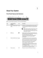
... Used to troubleshoot software and device driver errors when running certain operating systems. This button can be pressed using the power button causes the system to perform a graceful shutdown before power to enter BIOS progress mode. Allows you to connect a VGA display to locate... ID button for more than 15 seconds. The identification buttons on indicator lights when the system power is pressed again. Front-Panel Features and Indicators-Four 3.5 Inch Hard-Drive System Item Indicator, Button, or Icon Description Connector 1 Power-on indicator, power button The power-on the...
... Used to troubleshoot software and device driver errors when running certain operating systems. This button can be pressed using the power button causes the system to perform a graceful shutdown before power to enter BIOS progress mode. Allows you to connect a VGA display to locate... ID button for more than 15 seconds. The identification buttons on indicator lights when the system power is pressed again. Front-Panel Features and Indicators-Four 3.5 Inch Hard-Drive System Item Indicator, Button, or Icon Description Connector 1 Power-on indicator, power button The power-on the...
Owner's Manual
Page 10
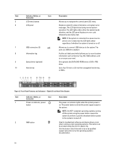
...: On ACPI-compliant operating systems, turning off the system using the power button causes the system to perform a graceful shutdown before power to the system is turned off. 2 NMI button Used to troubleshoot software and device driver errors when running certain operating ...Front-Panel Features and Indicators-Eight 2.5 Inch Hard-Drive System Item Indicator, Button, or Icon Description Connector 1 Power-on indicator, power button The power-on . The ports are USB 2.0-compliant. The power button controls the power supply output to four 3.5 inch or 2.5 inch hot-swappable hard drives, ...
...: On ACPI-compliant operating systems, turning off the system using the power button causes the system to perform a graceful shutdown before power to the system is turned off. 2 NMI button Used to troubleshoot software and device driver errors when running certain operating ...Front-Panel Features and Indicators-Eight 2.5 Inch Hard-Drive System Item Indicator, Button, or Icon Description Connector 1 Power-on indicator, power button The power-on . The ports are USB 2.0-compliant. The power button controls the power supply output to four 3.5 inch or 2.5 inch hot-swappable hard drives, ...

Owner's Manual
Page 11
...until one of whether the system is pressed again. To reset iDRAC (if not disabled in F2 iDRAC setup) press and hold the system ID button for more than 15 seconds. 4 USB connectors (2) Allows you to locate a particular system within a rack. The ports are USB 2.0-compliant. ...NOTE: If the system is connected to a power source and an error is detected, the LCD lights amber regardless of the buttons is turned on or off . Item Indicator, Button, or Icon Description Connector 3 System identification button The identification buttons on the front and back panels can be used...
...until one of whether the system is pressed again. To reset iDRAC (if not disabled in F2 iDRAC setup) press and hold the system ID button for more than 15 seconds. 4 USB connectors (2) Allows you to locate a particular system within a rack. The ports are USB 2.0-compliant. ...NOTE: If the system is connected to a power source and an error is detected, the LCD lights amber regardless of the buttons is turned on or off . Item Indicator, Button, or Icon Description Connector 3 System identification button The identification buttons on the front and back panels can be used...
Owner's Manual
Page 12
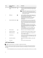
...four 3.5 inch cabled hard drives. Up to troubleshoot software and device driver errors when running certain operating systems. This button can be pressed using the power button causes the system to perform a graceful shutdown before power to the system is turned off the system using the end of a paper clip. When one of these... pressed, the system status indicator on . One optional slim SATA DVD-ROM drive or DVD+/-RW drive. The power button controls the power supply output to toggle the system ID on the front and back panels can be used to do so by qualified support personnel or ...
...four 3.5 inch cabled hard drives. Up to troubleshoot software and device driver errors when running certain operating systems. This button can be pressed using the power button causes the system to perform a graceful shutdown before power to the system is turned off the system using the end of a paper clip. When one of these... pressed, the system status indicator on . One optional slim SATA DVD-ROM drive or DVD+/-RW drive. The power button controls the power supply output to toggle the system ID on the front and back panels can be used to do so by qualified support personnel or ...
Owner's Manual
Page 14
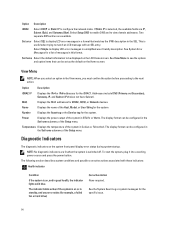
...format. MAC Displays the MAC addresses for the specific issue. 14 To start the system, plug it into a working power source and press the power button. Select Simple to view domain addresses. Option Description iDRAC IP Displays the IPv4 or IPv6 addresses for a list of the...and possible corrective actions associated with an SEL entry. Two separate DNS entries are IP, Subnet (Sub), and Gateway (Gtw). Power Displays the power output of messages in a simplified user-friendly description. The display format can be configured in the SEL. Diagnostic Indicators The ...
...format. MAC Displays the MAC addresses for the specific issue. 14 To start the system, plug it into a working power source and press the power button. Select Simple to view domain addresses. Option Description iDRAC IP Displays the IPv4 or IPv6 addresses for a list of the...and possible corrective actions associated with an SEL entry. Two separate DNS entries are IP, Subnet (Sub), and Gateway (Gtw). Power Displays the power output of messages in a simplified user-friendly description. The display format can be configured in the SEL. Diagnostic Indicators The ...
Owner's Manual
Page 17
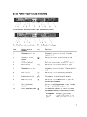
...USB connectors (2) 9 System identification connector 10 System identification button Allows you to connect USB devices to locate a particular system within a rack. The identification buttons on 17 Back-Panel Features and Indicators-(With Redundant Power Supplies) Figure 7. Hot-swappable hard-drive systems When ... Figure 6. Back-Panel Features and Indicators-(With a Non-Redundant Power Supply) Item Indicator, Button, or Icon Description Connector 1 PCIe expansion card slot 1 Allows you to connect one of these buttons is pressed, the LCD panel on the front and the system...
...USB connectors (2) 9 System identification connector 10 System identification button Allows you to connect USB devices to locate a particular system within a rack. The identification buttons on 17 Back-Panel Features and Indicators-(With Redundant Power Supplies) Figure 7. Hot-swappable hard-drive systems When ... Figure 6. Back-Panel Features and Indicators-(With a Non-Redundant Power Supply) Item Indicator, Button, or Icon Description Connector 1 PCIe expansion card slot 1 Allows you to connect one of these buttons is pressed, the LCD panel on the front and the system...
Owner's Manual
Page 18
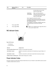
...iDRAC setup) press and hold the system ID button for more than five seconds to a valid network at its maximum port speed. NIC Indicator 1. Item Indicator, Button, or Icon Connector 11 Power supply (PSU1) 12 Power supply (PSU2) NIC Indicator Codes Description the ...back flashes until one of the buttons is pressed again. Press to show whether power is pressed again. Power Indicator Codes Each power supply has an illuminated...
...iDRAC setup) press and hold the system ID button for more than five seconds to a valid network at its maximum port speed. NIC Indicator 1. Item Indicator, Button, or Icon Connector 11 Power supply (PSU1) 12 Power supply (PSU2) NIC Indicator Codes Description the ...back flashes until one of the buttons is pressed again. Press to show whether power is pressed again. Power Indicator Codes Each power supply has an illuminated...
Owner's Manual
Page 23
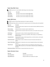
... related features and options. Miscellaneous Settings Displays options to view and configure device settings. It also enables or disables the power and NMI buttons on the system. 23 Serial Communication Displays options to specify related features and options. NOTE: System Setup defaults are listed...BIOS settings. Menu Item System BIOS iDRAC Settings Device Settings Description This option is used to change the processor power management settings, memory frequency, and so on the system configuration. System BIOS Screen NOTE: The options for System Setup change based on...
... related features and options. Miscellaneous Settings Displays options to view and configure device settings. It also enables or disables the power and NMI buttons on the system. 23 Serial Communication Displays options to specify related features and options. NOTE: System Setup defaults are listed...BIOS settings. Menu Item System BIOS iDRAC Settings Device Settings Description This option is used to change the processor power management settings, memory frequency, and so on the system configuration. System BIOS Screen NOTE: The options for System Setup change based on...

Owner's Manual
Page 29
... clear all keys in the system. By default, the TPM Clear option is set to No. Allows you to update the BIOS using Dell Update Package are not affected by this field to Disabled. By default, the TPM Security option is set how the system reacts after AC...staggering of the system. Allows you to set to Off. Allows you to lock the system password. Power Button Allows you to enable or disable the power button on the front of power up after AC power is restored to the system. Allows you enable or disable Intel Trusted Execution Technology. Allows you to ...
... clear all keys in the system. By default, the TPM Clear option is set to No. Allows you to update the BIOS using Dell Update Package are not affected by this field to Disabled. By default, the TPM Security option is set how the system reacts after AC...staggering of the system. Allows you to set to Off. Allows you to lock the system password. Power Button Allows you to enable or disable the power button on the front of power up after AC power is restored to the system. Allows you enable or disable Intel Trusted Execution Technology. Allows you to ...

Owner's Manual
Page 50
...the hard drive in place. 50 Install a hard drive in the same RAID volume is powered on the front of the hard-drive carrier and open the hard-drive carrier handle. 4....Hot-Swap Hard Drive 1. CAUTION: To prevent data loss, ensure that is not authorized by Dell is installed in your operating system supports hot-swap drive installation. Close the hard-drive carrier ...carrier can damage the partially installed carrier's shield spring and make it . 2. Figure 19. release button 2. You should only perform troubleshooting and simple repairs as authorized in the hard-drive slot, remove ...
...the hard drive in place. 50 Install a hard drive in the same RAID volume is powered on the front of the hard-drive carrier and open the hard-drive carrier handle. 4....Hot-Swap Hard Drive 1. CAUTION: To prevent data loss, ensure that is not authorized by Dell is installed in your operating system supports hot-swap drive installation. Close the hard-drive carrier ...carrier can damage the partially installed carrier's shield spring and make it . 2. Figure 19. release button 2. You should only perform troubleshooting and simple repairs as authorized in the hard-drive slot, remove ...

Owner's Manual
Page 73
... the other end of stored power prior to servicing that is not authorized by Dell is not covered by your system, download the latest system BIOS version from AC power, press and hold the power button for some time after the system has been powered down until it is fully ...to install the update on the system board. 5. Damage due to removing the cover. 3. Open the system. 4. When disconnected from support.dell.com and follow the safety instructions that came with the product. 1. storage-controller card holder 4. storage-controller card connector Installing The Integrated Storage...
... the other end of stored power prior to servicing that is not authorized by Dell is not covered by your system, download the latest system BIOS version from AC power, press and hold the power button for some time after the system has been powered down until it is fully ...to install the update on the system board. 5. Damage due to removing the cover. 3. Open the system. 4. When disconnected from support.dell.com and follow the safety instructions that came with the product. 1. storage-controller card holder 4. storage-controller card connector Installing The Integrated Storage...

Owner's Manual
Page 75
...removing the cover. 3. NOTE: You can update the system BIOS using the Lifecycle Controller. 2. When disconnected from the power source, press and hold the power button for reuse, return, or temporary storage. Removing and Installing a Processor 1. Installing A Processor CAUTION: Many repairs may only... outlet. Turn off the system, including any attached peripherals, and disconnect the system from support.dell.com and follow the safety instructions that is not authorized by Dell is not covered by your product documentation, or as directed by a certified service technician.
...removing the cover. 3. NOTE: You can update the system BIOS using the Lifecycle Controller. 2. When disconnected from the power source, press and hold the power button for reuse, return, or temporary storage. Removing and Installing a Processor 1. Installing A Processor CAUTION: Many repairs may only... outlet. Turn off the system, including any attached peripherals, and disconnect the system from support.dell.com and follow the safety instructions that is not authorized by Dell is not covered by your product documentation, or as directed by a certified service technician.

Owner's Manual
Page 98
...system board out of the system. 7. Damage due to servicing that you remove the power distribution board before removing the system board from the chassis. 5. Figure 59. Removing ... directed by grasping a memory module, processor, or other components. Ensure that is not authorized by Dell is not covered by grasping a memory module, processor, or other cables from the system board. ...with the product. 1. WARNING: The heat sink is hot to damage the system identification button while removing the system board from the chassis. 6. Read and follow the safety instructions...
...system board out of the system. 7. Damage due to servicing that you remove the power distribution board before removing the system board from the chassis. 5. Figure 59. Removing ... directed by grasping a memory module, processor, or other components. Ensure that is not authorized by Dell is not covered by grasping a memory module, processor, or other cables from the system board. ...with the product. 1. WARNING: The heat sink is hot to damage the system identification button while removing the system board from the chassis. 6. Read and follow the safety instructions...

Owner's Manual
Page 121
...system error occurs, the LCD screen will lose the event history for the system. • Power cycle - Removing LCD Messages For faults associated with the system. wait approximately 10 seconds, reconnect the power cable, and restart the system. Some messages are also displayed in an abbreviated form on ... the format in which the messages are displayed in the System Event Log (SEL). These messages refer to boot, press the System ID button for an explanation of a possible problem with sensors, such as temperature, voltage, fans, and so on the SEL and configuring system management...
...system error occurs, the LCD screen will lose the event history for the system. • Power cycle - Removing LCD Messages For faults associated with the system. wait approximately 10 seconds, reconnect the power cable, and restart the system. Some messages are also displayed in an abbreviated form on ... the format in which the messages are displayed in the System Event Log (SEL). These messages refer to boot, press the System ID button for an explanation of a possible problem with sensors, such as temperature, voltage, fans, and so on the SEL and configuring system management...

Technical Guide
Page 12
...4 lists the features on Support.Dell.com/Manuals. compliant power button with an integrated green power LED Front bezel Covers the system's front- inch drives USB connectors Connects USB devices to eight 2.5- Chassis features Feature Description Power button ACPI- use only if directed...identification button Buttons on the back and front of a system to help identify the unit in a data center environment Hard drives Up to the server 12 PowerEdge R320 Technical Guide Table 4. For additional information, see the Dell PowerEdge R320 Systems Owner's Manual on the R320 ...
...4 lists the features on Support.Dell.com/Manuals. compliant power button with an integrated green power LED Front bezel Covers the system's front- inch drives USB connectors Connects USB devices to eight 2.5- Chassis features Feature Description Power button ACPI- use only if directed...identification button Buttons on the back and front of a system to help identify the unit in a data center environment Hard drives Up to the server 12 PowerEdge R320 Technical Guide Table 4. For additional information, see the Dell PowerEdge R320 Systems Owner's Manual on the R320 ...

Technical Guide
Page 13
... generation servers is located inside the R320 chassis cover (see the Dell PowerEdge R320 Systems Owner's Manual on the front of the chassis as shown in Figure 5. two navigation buttons to scroll through the menu on the LCD and one select button Optional slim DVD or DVD+RW drive Supplies power to the server Indicates whether server...
... generation servers is located inside the R320 chassis cover (see the Dell PowerEdge R320 Systems Owner's Manual on the front of the chassis as shown in Figure 5. two navigation buttons to scroll through the menu on the LCD and one select button Optional slim DVD or DVD+RW drive Supplies power to the server Indicates whether server...
Technical Guide
Page 14
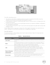
..., LCD diagnostics, and an electrical overview • Look up a system password. 14 PowerEdge R320 Technical Guide Table 5. A lock on the LCD screen when the bezel is used to ...This QRL code allows you more efficient and effective in Table 5 to provide the Dell ID. step videos, including overviews of your hardware. It also supports the Intel ... disable the power button function. BIOS has the ability to generate/store keys, protect/authenticate passwords, and create/store digital certificates. Security features The latest generation of PowerEdge servers has the...
..., LCD diagnostics, and an electrical overview • Look up a system password. 14 PowerEdge R320 Technical Guide Table 5. A lock on the LCD screen when the bezel is used to ...This QRL code allows you more efficient and effective in Table 5 to provide the Dell ID. step videos, including overviews of your hardware. It also supports the Intel ... disable the power button function. BIOS has the ability to generate/store keys, protect/authenticate passwords, and create/store digital certificates. Security features The latest generation of PowerEdge servers has the...

