
User Manual
Page 3
Figure 1. Installation And Configuration WARNING: Before performing the following the safety instructions and the rack installation instructions provided with the system. Assemble the rails and install the system in a Rack 3 Unpacking A Rack System Unpack your system. Installing the Rails and System in the rack following procedure, review the safety instructions that came with your system and identify each item.
Figure 1. Installation And Configuration WARNING: Before performing the following the safety instructions and the rack installation instructions provided with the system. Assemble the rails and install the system in a Rack 3 Unpacking A Rack System Unpack your system. Installing the Rails and System in the rack following procedure, review the safety instructions that came with your system and identify each item.

Owner's Manual
Page 53
...Removing A Hard Drive Or A Hard-Drive Adapter From A Hard-Drive Carrier 1. Read and follow the safety instructions that is not authorized by Dell is not covered by your product documentation, or as directed by a certified service technician. screws (4) 3. screw holes (4) 53 Align the screw... holes on the 2.5 inch hard drive with the product. 1. Remove the screws from the slide rails on the 3.5 inch hard-drive adapter. 2. Figure 22. Damage due to the hard-drive adapter. Removing and Installing a Hot-Swap Hard Drive Into a...
...Removing A Hard Drive Or A Hard-Drive Adapter From A Hard-Drive Carrier 1. Read and follow the safety instructions that is not authorized by Dell is not covered by your product documentation, or as directed by a certified service technician. screws (4) 3. screw holes (4) 53 Align the screw... holes on the 2.5 inch hard drive with the product. 1. Remove the screws from the slide rails on the 3.5 inch hard-drive adapter. 2. Figure 22. Damage due to the hard-drive adapter. Removing and Installing a Hot-Swap Hard Drive Into a...
Technical Guide
Page 3
...PowerEdge R320 Technical Guide Additional specifications...44 Chassis dimensions and weight ...44 Video specifications ...44 Environmental specifications ...45 Power supply specifications ...46 Rack rail specifications ...46 USB peripherals ...47 Appendix B. Table of contents 1 System overview...5 Introduction ...5 New technologies ...6 2 System features ...7 Comparison of PowerEdge......26 Power supply units ...27 Thermal and acoustics...28 9 Rack rails and cable management ...31 Sliding and static rail systems ...31 Cable management arm...33 10 Operating systems and virtualization ...
...PowerEdge R320 Technical Guide Additional specifications...44 Chassis dimensions and weight ...44 Video specifications ...44 Environmental specifications ...45 Power supply specifications ...46 Rack rail specifications ...46 USB peripherals ...47 Appendix B. Table of contents 1 System overview...5 Introduction ...5 New technologies ...6 2 System features ...7 Comparison of PowerEdge......26 Power supply units ...27 Thermal and acoustics...28 9 Rack rails and cable management ...31 Sliding and static rail systems ...31 Cable management arm...33 10 Operating systems and virtualization ...

Technical Guide
Page 4
...Supported hard drives ...21 Table 12. Power supply efficiency ...28 Table 18. to PowerEdge R320 7 Table 3. Supported video modes...44 Table 26. Industry standard documents ...48 Table 30. Dell systems management solutions...36 Figure 11. Systems management server lifecycle ...42 Figure 12. ...NICs and HBAs ...25 Table 16. Appendix C. Primary operating system support ...34 Table 21. Additional resources ...49 Figures Figure 1. Static rails ...32 Figure 10. Memory technologies supported...17 Table 8. Power tools and technologies ...26 Table 17. Internal view ...12 Figure 5. ...
...Supported hard drives ...21 Table 12. Power supply efficiency ...28 Table 18. to PowerEdge R320 7 Table 3. Supported video modes...44 Table 26. Industry standard documents ...48 Table 30. Dell systems management solutions...36 Figure 11. Systems management server lifecycle ...42 Figure 12. ...NICs and HBAs ...25 Table 16. Appendix C. Primary operating system support ...34 Table 21. Additional resources ...49 Figures Figure 1. Static rails ...32 Figure 10. Memory technologies supported...17 Table 8. Power tools and technologies ...26 Table 17. Internal view ...12 Figure 5. ...

Technical Guide
Page 10
... on the specific versions and additions, visit Dell.com/OSsupport. 1GB means 1 billion bytes and TB equals 1 trillion bytes; less cable management arm • ReadyRails static rails for tool- actual capacity varies with support for optional tool- Feature PowerEdge R320 technical specification Rack support • ReadyRailsTM II sliding rails for tool- post racks with square...
... on the specific versions and additions, visit Dell.com/OSsupport. 1GB means 1 billion bytes and TB equals 1 trillion bytes; less cable management arm • ReadyRails static rails for tool- actual capacity varies with support for optional tool- Feature PowerEdge R320 technical specification Rack support • ReadyRailsTM II sliding rails for tool- post racks with square...

Technical Guide
Page 31
... very quickly and easily. Both rail systems also support tooled mounting in 2- Figure 8 shows the sliding rails with optional CMA 31 PowerEdge R320 Technical Guide The rails ship in the tool- The sliding rail system allows you to the R310 sliding rails that supports the wide system chassis... with the ReadyRails II mounting interface. The sliding rails are available with square or unthreaded round mounting holes. Compared to fully extend the server out the rack for easy access for the Dell PowerEdge R320 provide tool- 9 Rack rails and cable management The sliding and static...
... very quickly and easily. Both rail systems also support tooled mounting in 2- Figure 8 shows the sliding rails with optional CMA 31 PowerEdge R320 Technical Guide The rails ship in the tool- The sliding rail system allows you to the R310 sliding rails that supports the wide system chassis... with the ReadyRails II mounting interface. The sliding rails are available with square or unthreaded round mounting holes. Compared to fully extend the server out the rack for easy access for the Dell PowerEdge R320 provide tool- 9 Rack rails and cable management The sliding and static...

Technical Guide
Page 32
... as the more information on installing the R320 in threaded hole 4- Both the sliding rails and the static rails support tool- Table 19 lists the rack types that the R320 supports. For detailed information about static and sliding rails, see the Rack Installation Instructions on Support.Dell.com/Manuals. 32 PowerEdge R320 Technical Guide less mounting in Appendix...
... as the more information on installing the R320 in threaded hole 4- Both the sliding rails and the static rails support tool- Table 19 lists the rack types that the R320 supports. For detailed information about static and sliding rails, see the Rack Installation Instructions on Support.Dell.com/Manuals. 32 PowerEdge R320 Technical Guide less mounting in Appendix...

Technical Guide
Page 46
... and over the entire system ambient operating range, the inrush current may reach 55A per power supply for the PowerEdge R320. Rack rail specifications Table 28 lists the spacing dimensions for the R320 sliding and static rails. Table 28. Maximum shock Operating Half sine shock in all operational orientations of 31G +/- 5% with a pulse duration of... contaminant level Class G1 or lower as defined by ISA- square wave shock on all six sides of 2ms +/- 10%; The adjustment range of the rails is a function of the type of the rails 46 PowerEdge R320 Technical Guide Table 27.
... and over the entire system ambient operating range, the inrush current may reach 55A per power supply for the PowerEdge R320. Rack rail specifications Table 28 lists the spacing dimensions for the R320 sliding and static rails. Table 28. Maximum shock Operating Half sine shock in all operational orientations of 31G +/- 5% with a pulse duration of... contaminant level Class G1 or lower as defined by ISA- square wave shock on all six sides of 2ms +/- 10%; The adjustment range of the rails is a function of the type of the rails 46 PowerEdge R320 Technical Guide Table 27.

Technical Guide
Page 49
... with the CMA kits. Additional resources Resource Description of documents and websites that provide for more information on the rails. The document provides the instructions for installing the cable management arm on the Dell PowerEdge R320. The document provides the instructions for installing the server in HTML format on system updates. Appendix C. Additional resources...
... with the CMA kits. Additional resources Resource Description of documents and websites that provide for more information on the rails. The document provides the instructions for installing the cable management arm on the Dell PowerEdge R320. The document provides the instructions for installing the server in HTML format on system updates. Appendix C. Additional resources...

Cable Routing Procedures
Page 3
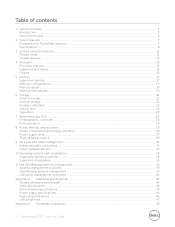
Replacing a hot swap power supply with a CMA 4 1.1. Replacing the outer power supply 9 Figure 10. Cabling a system installed in static rails 11 3 Cable Routing Procedures for Dell PowerEdge R320 & R420 Systems Contents Introduction ...4 Section 1: Cabling a PowerEdge R320 or R420 system with a left-side mounted CMA 8 2.2. Connecting the cables to the system 4 1.2. Attaching the inner CMA attachment bracket 6 Figure...
Replacing a hot swap power supply with a CMA 4 1.1. Replacing the outer power supply 9 Figure 10. Cabling a system installed in static rails 11 3 Cable Routing Procedures for Dell PowerEdge R320 & R420 Systems Contents Introduction ...4 Section 1: Cabling a PowerEdge R320 or R420 system with a left-side mounted CMA 8 2.2. Connecting the cables to the system 4 1.2. Attaching the inner CMA attachment bracket 6 Figure...
Cable Routing Procedures
Page 4
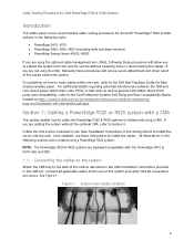
... 4 If you are not using a CMA. Connect all applicable cables to the rear of the rails as general information about third party rack compatibility, refer to install the server into the rack. Cable Routing Procedures for Dell PowerEdge R320 & R420 Systems Introduction This white paper covers recommended cable routing procedures for Rack Enclosure white...
... 4 If you are not using a CMA. Connect all applicable cables to the rear of the rails as general information about third party rack compatibility, refer to install the server into the rack. Cable Routing Procedures for Dell PowerEdge R320 & R420 Systems Introduction This white paper covers recommended cable routing procedures for Rack Enclosure white...
Cable Routing Procedures
Page 5
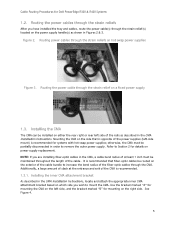
...left -side mount) is opposite of the CMA is recommended. 1.3.1. Installing the CMA The CMA can be maintained throughout the length of the rails as shown in the CMA, a cable bend radius of at the entrance and exit of the power supplies (left side, and the bracket... side you have installed the tray and cables, route the power cable(s) through the strain reliefs After you wish to Section 2 for Dell PowerEdge R320 & R420 Systems 1.2. Installing the inner CMA attachment bracket As described in the CMA Installation Instructions. Cable Routing Procedures for details on power supply...
...left -side mount) is opposite of the CMA is recommended. 1.3.1. Installing the CMA The CMA can be maintained throughout the length of the rails as shown in the CMA, a cable bend radius of at the entrance and exit of the power supplies (left side, and the bracket... side you have installed the tray and cables, route the power cable(s) through the strain reliefs After you wish to Section 2 for Dell PowerEdge R320 & R420 Systems 1.2. Installing the inner CMA attachment bracket As described in the CMA Installation Instructions. Cable Routing Procedures for details on power supply...

Cable Routing Procedures
Page 6
... inside the CMA. If the KVM SIP will not fit inside the CMA basket for Dell PowerEdge R320 & R420 Systems Figure 4. Clip off the excess length of the CMA using the hook-and-loop straps provided on the rails. 2. Cable Routing Procedures for light to medium cable loads. Routing the cables through the ...SIP), it to the exterior of the front basket as shown in the CMA kit. 5. Cables entering the CMA should have routed all of the rails by attaching both CMA housings to the closed (retracted) position. 6 Install the CMA on the rear left side of the cables through the CMA ...
... inside the CMA. If the KVM SIP will not fit inside the CMA basket for Dell PowerEdge R320 & R420 Systems Figure 4. Clip off the excess length of the CMA using the hook-and-loop straps provided on the rails. 2. Cable Routing Procedures for light to medium cable loads. Routing the cables through the ...SIP), it to the exterior of the front basket as shown in the CMA kit. 5. Cables entering the CMA should have routed all of the rails by attaching both CMA housings to the closed (retracted) position. 6 Install the CMA on the rear left side of the cables through the CMA ...

Cable Routing Procedures
Page 7
...the same as described in the cables on the rear right side of the rails by attaching both ends of the rack to the attachment brackets on the rails. Right-side mounted CMA installation 7 Right-side mounting instructions Install the CMA on... both CMA housings to verify that there is sufficient slack in Section 1.3.2. See Figure 7 for an example of a completed right-side mounted CMA installation. See Figure 6 for an example of a completed left -side mounting as for Dell PowerEdge R320...
...the same as described in the cables on the rear right side of the rails by attaching both ends of the rack to the attachment brackets on the rails. Right-side mounted CMA installation 7 Right-side mounting instructions Install the CMA on... both CMA housings to verify that there is sufficient slack in Section 1.3.2. See Figure 7 for an example of a completed right-side mounted CMA installation. See Figure 6 for an example of a completed left -side mounting as for Dell PowerEdge R320...
Cable Routing Procedures
Page 8
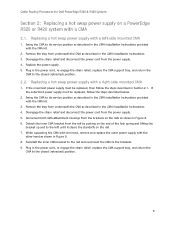
... with the CMA kit. 3. Replacing a hot swap power supply with a CMA 2.1. Cable Routing Procedures for Dell PowerEdge R320 & R420 Systems Section 2: Replacing a hot swap power supply on a PowerEdge R320 or R420 system with a left until it clears the standoffs on the rail. 7. If the outermost power supply must be replaced, follow the steps described in Figure 9. 8.
... with the CMA kit. 3. Replacing a hot swap power supply with a CMA 2.1. Cable Routing Procedures for Dell PowerEdge R320 & R420 Systems Section 2: Replacing a hot swap power supply on a PowerEdge R320 or R420 system with a left until it clears the standoffs on the rail. 7. If the outermost power supply must be replaced, follow the steps described in Figure 9. 8.
Cable Routing Procedures
Page 10
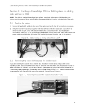
... screwdriver to remove the screws that all cables disconnected before it can be removed from the sliding rails if necessary in Figure 11. Removing the outer CMA brackets for the Dell PowerEdge R320 & R420 is optional. Connect all applicable cables to the right outer CMA bracket (as shown ...in order to allow the rails to the rack frame if desired. Figure 11. Cable routing on sliding rails without a CMA 3.2. Without the CMA...
... screwdriver to remove the screws that all cables disconnected before it can be removed from the sliding rails if necessary in Figure 11. Removing the outer CMA brackets for the Dell PowerEdge R320 & R420 is optional. Connect all applicable cables to the right outer CMA bracket (as shown ...in order to allow the rails to the rack frame if desired. Figure 11. Cable routing on sliding rails without a CMA 3.2. Without the CMA...
Cable Routing Procedures
Page 11
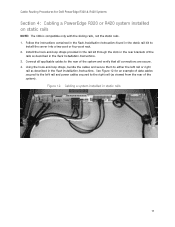
... in the Rack Installation Instructions. See Figure 12 for Dell PowerEdge R320 & R420 Systems Section 4: Cabling a PowerEdge R320 or R420 system installed on static rails NOTE: The CMA is compatible only with the sliding rails, not the static rails. 1. Install the hook-and-loop straps provided in the rail kit through the slots in the rear brackets of the...
... in the Rack Installation Instructions. See Figure 12 for Dell PowerEdge R320 & R420 Systems Section 4: Cabling a PowerEdge R320 or R420 system installed on static rails NOTE: The CMA is compatible only with the sliding rails, not the static rails. 1. Install the hook-and-loop straps provided in the rail kit through the slots in the rear brackets of the...


