User Manual
Page 7
.... CAUTION: Instructions for Rack-Mounted Systems: • Your rack kit has been approved only for specific caution statements and procedures. It is your responsibility to be components in the rack. Information includes assembling the rack, coupling two racks, and routing cables through this document or as to help protect your system. Installation Guide 5 Safety Instructions Use the following precautions for trained service technicians installing a rack enclosure. SAFETY: Rack Mounting of...
.... CAUTION: Instructions for Rack-Mounted Systems: • Your rack kit has been approved only for specific caution statements and procedures. It is your responsibility to be components in the rack. Information includes assembling the rack, coupling two racks, and routing cables through this document or as to help protect your system. Installation Guide 5 Safety Instructions Use the following precautions for trained service technicians installing a rack enclosure. SAFETY: Rack Mounting of...

User Manual
Page 14
... panel. 3 Lift the panel upward until both latches lock into the rack until the panel lip clears the top of the panel downward onto the rack. 3 Press the panel into place. 12 Installation Guide Removing and Replacing the Side Panels CAUTION: For stand-alone racks, reinstalling the side panels is not mandatory for installing systems in a rack, having the sides open makes it easier to install slide assemblies and support rails...
... panel. 3 Lift the panel upward until both latches lock into the rack until the panel lip clears the top of the panel downward onto the rack. 3 Press the panel into place. 12 Installation Guide Removing and Replacing the Side Panels CAUTION: For stand-alone racks, reinstalling the side panels is not mandatory for installing systems in a rack, having the sides open makes it easier to install slide assemblies and support rails...

User Manual
Page 33
... (bottom) 3 2 plunger (2 per bar) Installation Guide 31 Removing and Installing the Back Door Stabilizer Bars The top and bottom bars used to stabilize the back doors can be removed, making it easier to route cables through the top and bottom of the rack. 1 Open the back doors. 2 Pull and hold the ...plungers on each side of the bar, and pull the bar up and away from the rack (see Figure 1-18). 3 After routing your cables, replace...
... (bottom) 3 2 plunger (2 per bar) Installation Guide 31 Removing and Installing the Back Door Stabilizer Bars The top and bottom bars used to stabilize the back doors can be removed, making it easier to route cables through the top and bottom of the rack. 1 Open the back doors. 2 Pull and hold the ...plungers on each side of the bar, and pull the bar up and away from the rack (see Figure 1-18). 3 After routing your cables, replace...
Dell PowerEdge 2420 Rack Installation Guide
Page 7
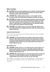
... installed using the recommended tools. Installation Instructions This installation guide provides instructions for the rack cabinet provided. For complete safety and regulatory information, see the safety instructions that installation of equipment with your responsibility to the rack installation documentation accompanying the system and the rack for specific caution statements and procedures. CAUTION: Instructions for Rack-Mounted Systems: • Your rack kit has been approved only for trained service technicians installing a 24-unit (U) rack...
... installed using the recommended tools. Installation Instructions This installation guide provides instructions for the rack cabinet provided. For complete safety and regulatory information, see the safety instructions that installation of equipment with your responsibility to the rack installation documentation accompanying the system and the rack for specific caution statements and procedures. CAUTION: Instructions for Rack-Mounted Systems: • Your rack kit has been approved only for trained service technicians installing a 24-unit (U) rack...

Dell PowerEdge 2420 Rack Installation Guide
Page 28
... bars used to stabilize the back doors can be removed, making it easier to route cables through the top and bottom of the rack. 1 Open the back doors. 2 Pull and hold the plungers on each side of the bar, and pull the bar up and away from the rack (see Figure 1-16). 3 After routing your cables, replace the...
... bars used to stabilize the back doors can be removed, making it easier to route cables through the top and bottom of the rack. 1 Open the back doors. 2 Pull and hold the plungers on each side of the bar, and pull the bar up and away from the rack (see Figure 1-16). 3 After routing your cables, replace the...
User Manual
Page 7
SAFETY: Rack Mounting of system and rack complies with all liability and warranties in a Dell rack cabinet using the customer rack kit. NOTE: Your system is your responsibility to ensure that shipped with such combinations. • System rack kits are considered to be installed in any system as well as a separate document. Dell™ PowerEdge™ 4210 Installation Guide 5 For complete safety and regulatory information, see the...
SAFETY: Rack Mounting of system and rack complies with all liability and warranties in a Dell rack cabinet using the customer rack kit. NOTE: Your system is your responsibility to ensure that shipped with such combinations. • System rack kits are considered to be installed in any system as well as a separate document. Dell™ PowerEdge™ 4210 Installation Guide 5 For complete safety and regulatory information, see the...
User Manual
Page 9
... as the safety instructions found in the rack. The cabinet has no brakes. The weight of more than one system out of the procedures for the current system before installing components in your rack with the slide assemblies fully extended. CAUTION: Do not attempt to others who may be involved. Dell™ PowerEdge™ 4210 Installation Guide 7 Your system...
... as the safety instructions found in the rack. The cabinet has no brakes. The weight of more than one system out of the procedures for the current system before installing components in your rack with the slide assemblies fully extended. CAUTION: Do not attempt to others who may be involved. Dell™ PowerEdge™ 4210 Installation Guide 7 Your system...
User Manual
Page 10
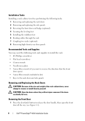
... the front door opens) • 5-mm Allen wrench (included in kit) • Keys to the rack doors and side panels Removing and Replacing the Rack Doors CAUTION: Because of the size and weight of the rack cabinet doors, never attempt to release the door handle, then open the front door all the way (see Figure 1-1). 8 Dell™ PowerEdge™ 4210 Installation Guide CAUTION: Store the...
... the front door opens) • 5-mm Allen wrench (included in kit) • Keys to the rack doors and side panels Removing and Replacing the Rack Doors CAUTION: Because of the size and weight of the rack cabinet doors, never attempt to release the door handle, then open the front door all the way (see Figure 1-1). 8 Dell™ PowerEdge™ 4210 Installation Guide CAUTION: Store the...
Cabling PowerEdge R815
Page 4
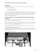
If you to install the server into the rack. Connect all connections are using a PowerEdge™ R815 system. See Figure 1. All illustrations in the rail kit to extend the system from the rack for service without the optional CMA, refer to the Dell Best Practices Guide for Rack Enclosure white paper. Figure 1: System with previous generation rails and CMAs. 1.1 Connecting the CMA Cables to the System Attach the...
If you to install the server into the rack. Connect all connections are using a PowerEdge™ R815 system. See Figure 1. All illustrations in the rail kit to extend the system from the rack for service without the optional CMA, refer to the Dell Best Practices Guide for Rack Enclosure white paper. Figure 1: System with previous generation rails and CMAs. 1.1 Connecting the CMA Cables to the System Attach the...
Cabling PowerEdge R810
Page 4
... how to route cables within the rack, refer to the Dell Best Practices Guide for service without the optional CMA, refer to the back of the system and verify that all connections are secure. Connect all applicable cables to install the server into the rack. All illustrations in the rail kit to the rear of the rails as described in the CMA Installation Instructions provided in the...
... how to route cables within the rack, refer to the Dell Best Practices Guide for service without the optional CMA, refer to the back of the system and verify that all connections are secure. Connect all applicable cables to install the server into the rack. All illustrations in the rail kit to the rear of the rails as described in the CMA Installation Instructions provided in the...
Cabling PowerEdge R715
Page 4
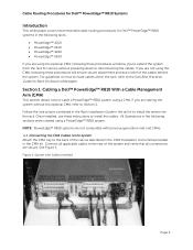
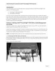
Section 1: Cabling a Dell™ PowerEdge™ R715 With a Cable Management Arm (CMA) This section details how to install the server into the rack. All illustrations in the following these procedures will allow you to extend the system from the rack for service without the optional CMA, refer to Section 2. See Figure 1. Follow the instructions contained in the Rack Installation Guide in the rail kit to cable a PowerEdge™ R715...
Section 1: Cabling a Dell™ PowerEdge™ R715 With a Cable Management Arm (CMA) This section details how to install the server into the rack. All illustrations in the following these procedures will allow you to extend the system from the rack for service without the optional CMA, refer to Section 2. See Figure 1. Follow the instructions contained in the Rack Installation Guide in the rail kit to cable a PowerEdge™ R715...

Cabling PowerEdge R710
Page 3
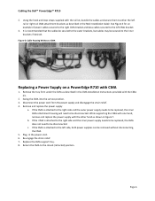
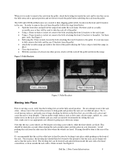
...Figure 2: Routing Power Cables Through the Strain Reliefs 3 2.3 Routing the Cables Through the CMA...3 Figure 3: Routing the Cables Through the CMA 4 Figure 4: Completed Left Side Mounted CMA Installation 5 Figure 5: Completed Right Side Mounted CMA Installation 5 Cabling a PowerEdge R710 Without a CMA ...5 3.1 Routing the Cables ...5 Figure 6: Cable Routing Without a CMA...6 Replacing a Power Supply on a PowerEdge R710 with CMA 6 Figure 7: Replacing Outer Power Supply ...7 Cabling a PowerEdge R710 Installed in Static Rails 7 Figure 8: Cabling a System Installed in Static Rails 7 Page 1
...Figure 2: Routing Power Cables Through the Strain Reliefs 3 2.3 Routing the Cables Through the CMA...3 Figure 3: Routing the Cables Through the CMA 4 Figure 4: Completed Left Side Mounted CMA Installation 5 Figure 5: Completed Right Side Mounted CMA Installation 5 Cabling a PowerEdge R710 Without a CMA ...5 3.1 Routing the Cables ...5 Figure 6: Cable Routing Without a CMA...6 Replacing a Power Supply on a PowerEdge R710 with CMA 6 Figure 7: Replacing Outer Power Supply ...7 Cabling a PowerEdge R710 Installed in Static Rails 7 Figure 8: Cabling a System Installed in Static Rails 7 Page 1
Cabling PowerEdge R710
Page 8
... need to the left CMA bracket. 3. Figure 6: Cable Routing Without a CMA Replacing a Power Supply on a PowerEdge R710 with the other hand as shown in the CMA Installation Instructions provided with the rail kit, bundle the cables and secure them to either the left side, both power supplies can be disconnected. c. Replace the CMA support tray. 8. Cabling the Dell™ PowerEdge™ R710 2. If the CMA is attached...
... need to the left CMA bracket. 3. Figure 6: Cable Routing Without a CMA Replacing a Power Supply on a PowerEdge R710 with the other hand as shown in the CMA Installation Instructions provided with the rail kit, bundle the cables and secure them to either the left side, both power supplies can be disconnected. c. Replace the CMA support tray. 8. Cabling the Dell™ PowerEdge™ R710 2. If the CMA is attached...

Cabling PowerEdge R610
Page 3
... Dongle to the CMA Basket 4 Figure 5: Completed Left Side Mounted CMA Installation 5 Figure 6: Completed Right Side Mounted CMA Installation 5 Cabling a PowerEdge R610 without a CMA ...6 3.1 Routing the Cables ...6 Figure 7: Cable Routing Without a CMA 6 3.1 Removing the CMA Brackets for Shallow Racks 6 Figure 8: Removing the CMA Brackets for Shallow Racks 6 Replacing a Power Supply on a PowerEdge R610 with CMA 7 Figure 9: Replacing Outer Power Supply 7 Cabling a PowerEdge R610 Installed in Static Rails 8 Figure 10: Cabling a System Installed in Static Rails 8 Page 1
... Dongle to the CMA Basket 4 Figure 5: Completed Left Side Mounted CMA Installation 5 Figure 6: Completed Right Side Mounted CMA Installation 5 Cabling a PowerEdge R610 without a CMA ...6 3.1 Routing the Cables ...6 Figure 7: Cable Routing Without a CMA 6 3.1 Removing the CMA Brackets for Shallow Racks 6 Figure 8: Removing the CMA Brackets for Shallow Racks 6 Replacing a Power Supply on a PowerEdge R610 with CMA 7 Figure 9: Replacing Outer Power Supply 7 Cabling a PowerEdge R610 Installed in Static Rails 8 Figure 10: Cabling a System Installed in Static Rails 8 Page 1
Cabling PowerEdge R610
Page 9
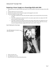
Cabling the Dell™ PowerEdge™ R610 Replacing a Power Supply on a PowerEdge R610 with the CMA kit. 2. Swing the CMA into the service position. 3. Remove and replace the power supply a. If the CMA is attached to the right side and the inner power supply needs to be replaced, the CMA does not need to be removed without disconnecting the CMA. Disconnect the power cord from under the CMA as...
Cabling the Dell™ PowerEdge™ R610 Replacing a Power Supply on a PowerEdge R610 with the CMA kit. 2. Swing the CMA into the service position. 3. Remove and replace the power supply a. If the CMA is attached to the right side and the inner power supply needs to be replaced, the CMA does not need to be removed without disconnecting the CMA. Disconnect the power cord from under the CMA as...
Best Practices Guide for Rack Enclosures
Page 4
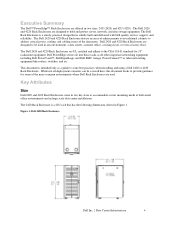
... an array of enhancements over traditional cabinets to provide guidance for 19" rackmount equipment. Dell PowerEdge servers fit into these racks as a guide to accommodate server mounting needs at both small office environments and in any environment: a data center, a remote office, a wiring closet, or even a factory floor. This document is solidly built and delivered with Dell quality service, support, and reliability. Key Attributes Size Dell 2420...
... an array of enhancements over traditional cabinets to provide guidance for 19" rackmount equipment. Dell PowerEdge servers fit into these racks as a guide to accommodate server mounting needs at both small office environments and in any environment: a data center, a remote office, a wiring closet, or even a factory floor. This document is solidly built and delivered with Dell quality service, support, and reliability. Key Attributes Size Dell 2420...
Best Practices Guide for Rack Enclosures
Page 8
...Using a 13mm wrench or socket set, remove the bolts attaching the front L-brackets to the rack frame. • Using a 17mm wrench or socket set, remove the bolts attaching the front L-brackets to the pallet. Do not attempt to move the rack with a 12mm wrench. Note that the rack be rolled into its final location... at the rear of the rack. Dell Inc. | Data Center Infrastructure 8 When you're ready to remove the rack from the pallet, check the leveling feet inside the rack with a flat head screwdriver, or from outside the rack with assistance to help guide and position the rack as it into...
...Using a 13mm wrench or socket set, remove the bolts attaching the front L-brackets to the rack frame. • Using a 17mm wrench or socket set, remove the bolts attaching the front L-brackets to the pallet. Do not attempt to move the rack with a 12mm wrench. Note that the rack be rolled into its final location... at the rear of the rack. Dell Inc. | Data Center Infrastructure 8 When you're ready to remove the rack from the pallet, check the leveling feet inside the rack with a flat head screwdriver, or from outside the rack with assistance to help guide and position the rack as it into...

Deployment Guide
Page 4
... selection part of text-mode setup. NOTE: Dell recommends installing the latest software updates and security patches for Installation of the Broadcom NetXtreme II (5708 based) network adapters which were deployed on http://support.microsoft.com/kb/896536. Drive Lettering Warning: Since the 11th Generation PowerEdge servers contain an embedded storage device, Microsoft Windows 2003 may see Best Practices for your operating system, RAID, and to download drivers and firmware updates. Older versions of the Dell...
... selection part of text-mode setup. NOTE: Dell recommends installing the latest software updates and security patches for Installation of the Broadcom NetXtreme II (5708 based) network adapters which were deployed on http://support.microsoft.com/kb/896536. Drive Lettering Warning: Since the 11th Generation PowerEdge servers contain an embedded storage device, Microsoft Windows 2003 may see Best Practices for your operating system, RAID, and to download drivers and firmware updates. Older versions of the Dell...

Deployment Guide
Page 5
... to add this time; PowerEdge Deployment Guide Dell Systems Build and Update Utility (SBUU) The SBUU is a collection of utilities that item. 6) When prompted, remove the SBUU DVD and insert the operating system DVD. Click Continue after answering each question. 5) Select any options you can be used to configure RAID, as well as a part of the operating system installation process. 9) The operating system and required drivers should boot to the hard drive at...
... to add this time; PowerEdge Deployment Guide Dell Systems Build and Update Utility (SBUU) The SBUU is a collection of utilities that item. 6) When prompted, remove the SBUU DVD and insert the operating system DVD. Click Continue after answering each question. 5) Select any options you can be used to configure RAID, as well as a part of the operating system installation process. 9) The operating system and required drivers should boot to the hard drive at...

Deployment Guide
Page 6
... Dell USB Key F6 Driver Utility. You may not be included, and therefore, the installation will fail since no hard drives will be other drivers that will also need to install the chipset, Broadcom NetXtreme II, and Matrox G200 video drivers. See the Microsoft documentation for more information. System will likely be seen. Please keep in mind that there will reboot in Device Manager. Remember that the network driver version...
... Dell USB Key F6 Driver Utility. You may not be included, and therefore, the installation will fail since no hard drives will be other drivers that will also need to install the chipset, Broadcom NetXtreme II, and Matrox G200 video drivers. See the Microsoft documentation for more information. System will likely be seen. Please keep in mind that there will reboot in Device Manager. Remember that the network driver version...

