Information Update - Processor Installation
Page 3
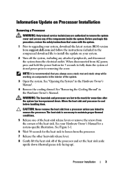
... sink and processor are authorized to remove the system cover and access any attached peripherals, and disconnect the system from support.dell.com and follow the instructions included in the interior of the system. 3 Open the system. The heat sink is recommended...version from the electrical outlet. Information Update on your Hardware Owner's Manual for a system-specific illustration. Before you begin this procedure, review the safety instructions that you intend to cool before handling them. Processor Installation 3 See "Removing the Cooling Shroud" in the Hardware Owner...
... sink and processor are authorized to remove the system cover and access any attached peripherals, and disconnect the system from support.dell.com and follow the instructions included in the interior of the system. 3 Open the system. The heat sink is recommended...version from the electrical outlet. Information Update on your Hardware Owner's Manual for a system-specific illustration. Before you begin this procedure, review the safety instructions that you intend to cool before handling them. Processor Installation 3 See "Removing the Cooling Shroud" in the Hardware Owner...
Information Update - Processor Installation
Page 6
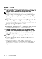
... from the packing material by the processor's edges only. NOTE: In a single-processor configuration, the CPU1 socket must be used. 1 If you begin this procedure, review the safety instructions that came with each pin 1 aligned and level. CAUTION: Positioning the processor incorrectly can permanently damage the system board or the processor...
... from the packing material by the processor's edges only. NOTE: In a single-processor configuration, the CPU1 socket must be used. 1 If you begin this procedure, review the safety instructions that came with each pin 1 aligned and level. CAUTION: Positioning the processor incorrectly can permanently damage the system board or the processor...

Getting Started Guide
Page 5
Installing the Rails and System in a Rack Assemble the rails and install the system in the rack following procedure, review the safety instructions that came with your enclosure. This section describes the steps required to set up your system and identify each item. Getting Started With Your System 3 Installation and Configuration WARNING: Before performing the following the safety instructions and the rack installation instructions provided with the system. Unpack the System Unpack your system for the first time.
Installing the Rails and System in a Rack Assemble the rails and install the system in the rack following procedure, review the safety instructions that came with your enclosure. This section describes the steps required to set up your system and identify each item. Getting Started With Your System 3 Installation and Configuration WARNING: Before performing the following the safety instructions and the rack installation instructions provided with the system. Unpack the System Unpack your system for the first time.
Getting Started Guide
Page 12
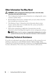
...first because they often supersede information in other documents. Dell™ offers comprehensive hardware training and certification. Other Information You May Need WARNING: Before performing the following procedure, review the safety instructions that came with your rack solution ...describes how to troubleshoot the system and install or replace system components. • Dell systems management application documentation provides information about installing ...
...first because they often supersede information in other documents. Dell™ offers comprehensive hardware training and certification. Other Information You May Need WARNING: Before performing the following procedure, review the safety instructions that came with your rack solution ...describes how to troubleshoot the system and install or replace system components. • Dell systems management application documentation provides information about installing ...
Dell PowerEdge M1000e Configuration Guide
Page 30
... correct, use a management station and and a local connection to the CMC, you can complete the initial CMC network configuration: 1 Log in to the Main Menu. - 5 Review the settings on the network using the CMC Web-based interface or CLI.
... correct, use a management station and and a local connection to the CMC, you can complete the initial CMC network configuration: 1 Log in to the Main Menu. - 5 Review the settings on the network using the CMC Web-based interface or CLI.
Hardware Owner's Manual
Page 20
NOTE: You cannot set a static IP address, use the CMC Web-based interface or RACADM. 5 Review the settings on the Network Summary screen. • If the settings are correct, press the center button to close the configuration wizard and return to ... the CMC network settings for DHCP. See the CMC User's Guide for the iDRAC using a management station and CLI commands. (For more information, see the PowerEdge M1000e Configuration Guide or CMC documentation.) NOTE: After you do not choose to a static address by either running the LCD Configuration Wizard, or by using...
NOTE: You cannot set a static IP address, use the CMC Web-based interface or RACADM. 5 Review the settings on the Network Summary screen. • If the settings are correct, press the center button to close the configuration wizard and return to ... the CMC network settings for DHCP. See the CMC User's Guide for the iDRAC using a management station and CLI commands. (For more information, see the PowerEdge M1000e Configuration Guide or CMC documentation.) NOTE: After you do not choose to a static address by either running the LCD Configuration Wizard, or by using...
Hardware Owner's Manual
Page 94
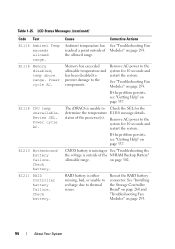
... AC. Cause Ambient temperature has reached a point outside of the processor(s). RAID battery is outside of the allowed range. E1116 Memory disabled, temp above range. Review SEL. Remove AC power to thermal issues. Remove AC power to the system for 10 seconds and restart the system. If the problem persists, see...
... AC. Cause Ambient temperature has reached a point outside of the processor(s). RAID battery is outside of the allowed range. E1116 Memory disabled, temp above range. Review SEL. Remove AC power to thermal issues. Remove AC power to the system for 10 seconds and restart the system. If the problem persists, see...
Hardware Owner's Manual
Page 99
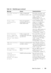
The system configuration requires more power than the power supplies can provide, even with throttling. Review & clear SEL. If the problem persists, see "Getting Help" on page 337. has been removed from the Check drive. E2010 Memory not ...E1710 I /O channel check. The system BIOS has reported an I /O channel check error. See "Troubleshooting Hard Drives" on page 297. system. Table 1-25. Review & clear SEL. Review & clear SEL. See "Troubleshooting Blade Memory" on page 298. Turn off power to the system for 10 seconds and restart the system. If the...
The system configuration requires more power than the power supplies can provide, even with throttling. Review & clear SEL. If the problem persists, see "Getting Help" on page 337. has been removed from the Check drive. E2010 Memory not ...E1710 I /O channel check. The system BIOS has reported an I /O channel check error. See "Troubleshooting Hard Drives" on page 297. system. Table 1-25. Review & clear SEL. Review & clear SEL. See "Troubleshooting Blade Memory" on page 298. Turn off power to the system for 10 seconds and restart the system. If the...
Hardware Owner's Manual
Page 102
... messages. E2021 Incorrect memory configuration. E2110 Multibit Error on page 297. The DIMM in slot "##" has had a multi-bit error (MBE). BIOS shutdown test failure. Review User Guide. Check screen message. Reseat DIMM. Power cycle AC. Check DIMMs. See "Troubleshooting Blade Memory" on DIMM ##. failure. Incorrect memory configuration. Check screen message...
... messages. E2021 Incorrect memory configuration. E2110 Multibit Error on page 297. The DIMM in slot "##" has had a multi-bit error (MBE). BIOS shutdown test failure. Review User Guide. Check screen message. Reseat DIMM. Power cycle AC. Check DIMMs. See "Troubleshooting Blade Memory" on DIMM ##. failure. Incorrect memory configuration. Check screen message...

Hardware Owner's Manual
Page 103
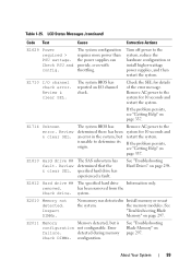
...Full. The SEL is rebooted. About Your System 103 Power cycle AC. I1912 SEL full. The system BIOS has Remove AC power to review all Errors. "##" represents the DIMM implicated by the BIOS. If the problem persists, see "Troubleshooting Blade Memory" on DIMM ##. LCD Status...(SBE) logging and restart the system. LCD overflow message. The eleventh message instructs the user to the system for details on DIMM ## & ##. Review & clear log. "## & ##" represents the DIMM pair implicated by the BIOS. Remove AC power to check the SEL for 10 seconds or clear...
...Full. The SEL is rebooted. About Your System 103 Power cycle AC. I1912 SEL full. The system BIOS has Remove AC power to review all Errors. "##" represents the DIMM implicated by the BIOS. If the problem persists, see "Troubleshooting Blade Memory" on DIMM ##. LCD Status...(SBE) logging and restart the system. LCD overflow message. The eleventh message instructs the user to the system for details on DIMM ## & ##. Review & clear log. "## & ##" represents the DIMM pair implicated by the BIOS. Remove AC power to check the SEL for 10 seconds or clear...
Hardware Owner's Manual
Page 119
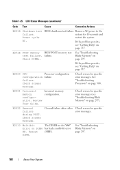
... encountered in the specified slot. ROM bad checksum = address Expansion card improperly Ensure that the expansion installed or faulty. Run the System Setup program and review the current settings. About Your System 119 Reseat the PCIe card in the specified slot number.
... encountered in the specified slot. ROM bad checksum = address Expansion card improperly Ensure that the expansion installed or faulty. Run the System Setup program and review the current settings. About Your System 119 Reseat the PCIe card in the specified slot number.

Dell Converged Enhanced Ethernet Administrator's Guide
Page 148
... to "Configuring IGMP" on page 128 or "Configuring IGMP snooping querier" on IGMP CLI commands. 130 Dell Converged Enhanced Ethernet Administrator's Guide 53-1002116-01 or - switch#show ip igmp snooping mrouter - When you have reviewed the IGMP statistics for all VLANs, or a specific VLAN. 15 Monitoring IGMP 4. switch#show ip igmp...
... to "Configuring IGMP" on page 128 or "Configuring IGMP snooping querier" on IGMP CLI commands. 130 Dell Converged Enhanced Ethernet Administrator's Guide 53-1002116-01 or - switch#show ip igmp snooping mrouter - When you have reviewed the IGMP statistics for all VLANs, or a specific VLAN. 15 Monitoring IGMP 4. switch#show ip igmp...

Dell M8428-k Hardware Reference Manual
Page 34
...SNMP messages to verify the LED state. 2. Browser-based GUI management is available through the Module's CLI errShow command. 22 Dell M8428-k Hardware Reference Manual 53-1001980-01 Because SSL is managed as a separate entity to beacon. Interpreting POST results The power...," next. Access this log through a secure browser using Secure Shell (SSH), a network security protocol for the Blade Server Enclosure. 3. Review the system log for a TCP/IP connection. The switch module OS supports the FibreAlliance Fibre Channel Management (FCMGMT) MIBs, allowing the provision...
...SNMP messages to verify the LED state. 2. Browser-based GUI management is available through the Module's CLI errShow command. 22 Dell M8428-k Hardware Reference Manual 53-1001980-01 Because SSL is managed as a separate entity to beacon. Interpreting POST results The power...," next. Access this log through a secure browser using Secure Shell (SSH), a network security protocol for the Blade Server Enclosure. 3. Review the system log for a TCP/IP connection. The switch module OS supports the FibreAlliance Fibre Channel Management (FCMGMT) MIBs, allowing the provision...

Web Tools Administrator’s Guide
Page 34
... installation on the confirmation dialog box. Click OK on the workstation 3. On the Java Control Panel, click View to open Java. 2. If you attempt to review the files that are in Figure 1 on the workstation. Click OK. 6. Use the following procedure to remove the temporary files used by Java applications. 4. Click...
... installation on the confirmation dialog box. Click OK on the workstation 3. On the Java Control Panel, click View to open Java. 2. If you attempt to review the files that are in Figure 1 on the workstation. Click OK. 6. Use the following procedure to remove the temporary files used by Java applications. 4. Click...

Web Tools Administrator’s Guide
Page 277
...: • To create a new configuration, click New. Optional: Select the check box corresponding to a port you want to block all ports you want to prohibit. Review your changes. Repeat this step for all ports. The cells in the matrix are displayed as empty, for Fabric OS based fabrics". 6. You cannot prohibit...
...: • To create a new configuration, click New. Optional: Select the check box corresponding to a port you want to block all ports you want to prohibit. Review your changes. Repeat this step for all ports. The cells in the matrix are displayed as empty, for Fabric OS based fabrics". 6. You cannot prohibit...
Fabric Watch Administrator’s Guide
Page 22
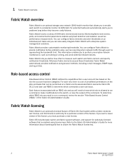
... potential network failures. Fabric Watch provides customizable monitoring thresholds. Fabric OS v6.1.0 and later use RBAC to determine which role is allowed to run a command, review the section "Role-Based Access Control (RBAC)" of the Fabric OS Administrator's Guide. You can issue. 1 Fabric Watch overview Fabric Watch overview Fabric Watch is...
... potential network failures. Fabric Watch provides customizable monitoring thresholds. Fabric OS v6.1.0 and later use RBAC to determine which role is allowed to run a command, review the section "Role-Based Access Control (RBAC)" of the Fabric OS Administrator's Guide. You can issue. 1 Fabric Watch overview Fabric Watch overview Fabric Watch is...

Fabric Watch Administrator’s Guide
Page 67
... not monitored. A high temperature indicates that the SFP might be in µwatts. Indicates whether the state of supplied current to GbE ports are reported, review the error log for any supporting data for SFP issues. SFP monitoring setting guidelines Use the SFP default settings. It is deteriorating. SFP class areas...
... not monitored. A high temperature indicates that the SFP might be in µwatts. Indicates whether the state of supplied current to GbE ports are reported, review the error log for any supporting data for SFP issues. SFP monitoring setting guidelines Use the SFP default settings. It is deteriorating. SFP class areas...

Fabric OS FCIP Administrator’s Guide
Page 107
... blocking factors. The Compression, Fastwrite, and Tape Pipelining settings must be opposite each other. FCIP tunnel issues 4 Refer to the Fabric OS Administrator's Guide to review the setup of available bandwidth resulting in the data path must match the opposite endpoint or the tunnel may not come up. Rule out all...
... blocking factors. The Compression, Fastwrite, and Tape Pipelining settings must be opposite each other. FCIP tunnel issues 4 Refer to the Fabric OS Administrator's Guide to review the setup of available bandwidth resulting in the data path must match the opposite endpoint or the tunnel may not come up. Rule out all...

Fabric OS Administrator’s Guide
Page 56
... about the commands used in a UNIX environment), and configure the application as HyperTerminal on the workstation. 2. To determine which role is allowed to run a command, review the section "Role-Based Access Control (RBAC)" on the workstation. After the IP address is associated with them. Connect the serial cable to the serial...
... about the commands used in a UNIX environment), and configure the application as HyperTerminal on the workstation. 2. To determine which role is allowed to run a command, review the section "Role-Based Access Control (RBAC)" on the workstation. After the IP address is associated with them. Connect the serial cable to the serial...
Fabric OS Administrator’s Guide
Page 95
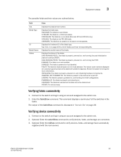
... below. LOADING: The blade is present, powered on , and loading the initial configuration. Verifying device connectivity 1. Connect to the switch and log in the fabric. Review the system error logs for a list of the blade. This command displays a summary of the blade type. CP BLADE: The blade is empty. Displays the...
... below. LOADING: The blade is present, powered on , and loading the initial configuration. Verifying device connectivity 1. Connect to the switch and log in the fabric. Review the system error logs for a list of the blade. This command displays a summary of the blade type. CP BLADE: The blade is empty. Displays the...


