Information Update - Intel Xeon 5600 Series Processors
Page 2
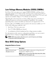
... BIOS configuration of both standard and low voltage memory modules For information on the memory configuration guidelines, see your system's Hardware Owner's Manual at a lower voltage may cause restrictions to PowerEdge R410, R510, R610, R710, R910, T410, T610, and T710 systems only. Low Voltage Memory Modules (DDR3L DIMMs) Intel Xeon 5600 series... up to control frequency and voltage configuration within allowable limits. NOTE: Applies to additional frequency and memory population capabilities. Operating the system memory at support.dell.com/manuals.
... BIOS configuration of both standard and low voltage memory modules For information on the memory configuration guidelines, see your system's Hardware Owner's Manual at a lower voltage may cause restrictions to PowerEdge R410, R510, R610, R710, R910, T410, T610, and T710 systems only. Low Voltage Memory Modules (DDR3L DIMMs) Intel Xeon 5600 series... up to control frequency and voltage configuration within allowable limits. NOTE: Applies to additional frequency and memory population capabilities. Operating the system memory at support.dell.com/manuals.
Information Update
Page 4
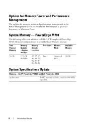
Total Physical Memory Memory Modules - Dell™ PowerEdge™ M905 and Dell PowerEdge M805 Architecture DDR2 memory modules, rated for memory power and performance management in your Hardware Owner's Manual. PowerEdge M710 The following table is an addition to Table 3-5 "Examples of PowerEdge M710 Memory Configurations" in the Power Management screen are Maximum Performance, a specified frequency, or Minimum Power...
Total Physical Memory Memory Modules - Dell™ PowerEdge™ M905 and Dell PowerEdge M805 Architecture DDR2 memory modules, rated for memory power and performance management in your Hardware Owner's Manual. PowerEdge M710 The following table is an addition to Table 3-5 "Examples of PowerEdge M710 Memory Configurations" in the Power Management screen are Maximum Performance, a specified frequency, or Minimum Power...

Information Update
Page 5
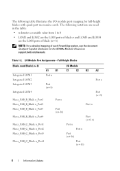
...: For a detailed mapping of each PowerEdge system, see the document Quadport Capable Hardware For the M1000e Modular Chassis on support.dell.com/manuals. Table 1-1. I/O Module Port Assignments-Half-Height Blades Blade n A1 Integrated LOM1 Port n Integrated LOM2 Mezz_FAB_B_Blade n_Port1 Mezz_FAB_B_Blade n_Port2 Mezz_FAB_B_Blade n_Port3 Mezz_FAB_B_Blade n_Port4 Mezz_FAB_C_Blade n_Port1 Mezz_FAB_C_Blade ...
...: For a detailed mapping of each PowerEdge system, see the document Quadport Capable Hardware For the M1000e Modular Chassis on support.dell.com/manuals. Table 1-1. I/O Module Port Assignments-Half-Height Blades Blade n A1 Integrated LOM1 Port n Integrated LOM2 Mezz_FAB_B_Blade n_Port1 Mezz_FAB_B_Blade n_Port2 Mezz_FAB_B_Blade n_Port3 Mezz_FAB_B_Blade n_Port4 Mezz_FAB_C_Blade n_Port1 Mezz_FAB_C_Blade ...
Information Update
Page 6
...; LOM1 and LOM2 are the LOM ports of blade n and LOM3 and LOM4 are the LOM ports of blade (n+8) NOTE: For a detailed mapping of each PowerEdge system, see the document Quadport Capable Hardware For the M1000e Modular Chassis on support...
...; LOM1 and LOM2 are the LOM ports of blade n and LOM3 and LOM4 are the LOM ports of blade (n+8) NOTE: For a detailed mapping of each PowerEdge system, see the document Quadport Capable Hardware For the M1000e Modular Chassis on support...
Information Update
Page 9
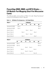
... I /O Module Port Mapping (Dual-Port Mezzanine Cards) The following tables correct portions of Table 1-12 in the "About Your System" section of your Hardware Owner's Manual. Table 1-4. I /O Module A1 B1 C1 C2 B2 A2 Port 4 Port 4 Port 12 Port 12 Port 4 Port 4 Port 4 Port 4 Port 12 Port 12 Port 12 Port...
... I /O Module Port Mapping (Dual-Port Mezzanine Cards) The following tables correct portions of Table 1-12 in the "About Your System" section of your Hardware Owner's Manual. Table 1-4. I /O Module A1 B1 C1 C2 B2 A2 Port 4 Port 4 Port 12 Port 12 Port 4 Port 4 Port 4 Port 4 Port 12 Port 12 Port 12 Port...
Information Update
Page 13
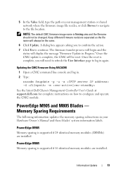
... Interface page to the file location. A dialog box appears asking you will be the same. 6 Click Update. PowerEdge M905 and M805 Blades - PowerEdge M805 Memory sparing is supported if 16 identical memory modules are installed. The firmware transfer process will begin and the status ... message "Firmware Update in . 2 Type: racadm fwupdate -g -u -a -d -m See the latest Dell Chassis Management Controller User's Guide at support.dell.com for complete instructions on your Hardware Owner's Manual and these blades' system information labels. 5 In the Value field, type the path on how to...
... Interface page to the file location. A dialog box appears asking you will be the same. 6 Click Update. PowerEdge M905 and M805 Blades - PowerEdge M805 Memory sparing is supported if 16 identical memory modules are installed. The firmware transfer process will begin and the status ... message "Firmware Update in . 2 Type: racadm fwupdate -g -u -a -d -m See the latest Dell Chassis Management Controller User's Guide at support.dell.com for complete instructions on your Hardware Owner's Manual and these blades' system information labels. 5 In the Value field, type the path on how to...
Information Update
Page 14
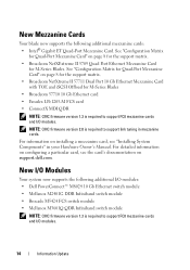
...see "Installing System Components" in mezzanine cards. NOTE: CMC firmware version 2.0 is required to support link tuning in your Hardware Owner's Manual. New I/O Modules Your system now supports the following additional mezzanine cards: • Intel® Gigabit ET Quad-Port Mezzanine Card. ...New Mezzanine Cards Your blade now supports the following additional I/O modules: • Dell PowerConnect™ M8024 10 Gb Ethernet switch module • Mellanox M2401G DDR Infiniband switch module • Brocade M5424 FC8 switch module &#...
...see "Installing System Components" in mezzanine cards. NOTE: CMC firmware version 2.0 is required to support link tuning in your Hardware Owner's Manual. New I/O Modules Your system now supports the following additional mezzanine cards: • Intel® Gigabit ET Quad-Port Mezzanine Card. ...New Mezzanine Cards Your blade now supports the following additional I/O modules: • Dell PowerConnect™ M8024 10 Gb Ethernet switch module • Mellanox M2401G DDR Infiniband switch module • Brocade M5424 FC8 switch module &#...
Information Update
Page 15
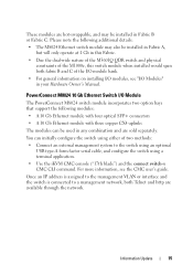
... the connect switch-n CMC CLI command. PowerConnect M8024 10 Gb Ethernet Switch I /O Modules" in Fabric B or Fabric C. You can be installed in your Hardware Owner's Manual. Information Update 15 For more information, see "I /O Module The PowerConnect M8024 switch module incorporates two option bays that support the following additional details: • The...
... the connect switch-n CMC CLI command. PowerConnect M8024 10 Gb Ethernet Switch I /O Modules" in Fabric B or Fabric C. You can be installed in your Hardware Owner's Manual. Information Update 15 For more information, see "I /O Module The PowerConnect M8024 switch module incorporates two option bays that support the following additional details: • The...

Information Update
Page 22
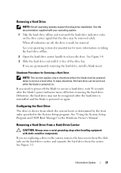
... 2 Insert the hard-drive carrier into place. If the drive carrier LED does not light, see "Troubleshooting SAS and SATA Drives" in your Hardware Owner's Manual. 22 Information Update Carefully align the channel on the hard drive carrier with the appropriate drive slot on the blade. 3 Push the drive carrier into...
... 2 Insert the hard-drive carrier into place. If the drive carrier LED does not light, see "Troubleshooting SAS and SATA Drives" in your Hardware Owner's Manual. 22 Information Update Carefully align the channel on the hard drive carrier with the appropriate drive slot on the blade. 3 Push the drive carrier into...
Information Update
Page 23
... a hard drive, wait 30 seconds after the hard drive is reinstalled and the blade is determined by the boot order specified in the Hardware Owner's Manual.
... a hard drive, wait 30 seconds after the hard drive is reinstalled and the blade is determined by the boot order specified in the Hardware Owner's Manual.
Information Update - M605, M600
Page 1
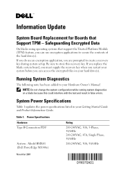
...an encryption application, you can use encryption applications to store this could interfere with the test and result in your hard drive(s). Model BMX01 (Dell PowerEdge M1000e) Rating 200-240VAC, 30A, 3-Phase, 50/60Hz 200-240VAC, 45A, Single Phase, 50/60Hz 200-240VAC, 30A, 50/60Hz ...listed in false errors. If you replace the blade system board, you must supply the recovery key when you restart your Hardware Owner's Manual. Information Update System Board Replacement for Boards that support the Trusted Platform Module (TPM) feature, you can access the encrypted files on...
...an encryption application, you can use encryption applications to store this could interfere with the test and result in your hard drive(s). Model BMX01 (Dell PowerEdge M1000e) Rating 200-240VAC, 30A, 3-Phase, 50/60Hz 200-240VAC, 45A, Single Phase, 50/60Hz 200-240VAC, 30A, 50/60Hz ...listed in false errors. If you replace the blade system board, you must supply the recovery key when you restart your Hardware Owner's Manual. Information Update System Board Replacement for Boards that support the Trusted Platform Module (TPM) feature, you can access the encrypted files on...
Information Update - M605, M600
Page 2
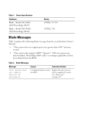
...8482; Opteron™ 2000 series processors. Table 1. Model 10G-TOM (Dell PowerEdge M600) Rating 12VDC, 33.33A 12VDC, 35A Blade Messages Table 2 updates the following blade messages listed in your Hardware Owner's Manual: • "This system does not support processors greater than 95W." Blade... Messages Message This system does not support Opteron SE processors. System halted. (PowerEdge M605 only)" is no longer applicable and has been ...
...8482; Opteron™ 2000 series processors. Table 1. Model 10G-TOM (Dell PowerEdge M600) Rating 12VDC, 33.33A 12VDC, 35A Blade Messages Table 2 updates the following blade messages listed in your Hardware Owner's Manual: • "This system does not support processors greater than 95W." Blade... Messages Message This system does not support Opteron SE processors. System halted. (PowerEdge M605 only)" is no longer applicable and has been ...
Information Update - Processor Installation
Page 3
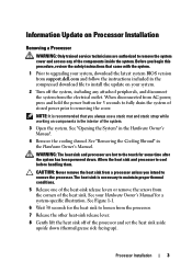
... heat sink and processor are authorized to remove the system cover and access any attached peripherals, and disconnect the system from support.dell.com and follow the instructions included in the interior of stored power prior to removing the cover. The heat sink is recommended that came... 3 Open the system. See your system. 2 Turn off of the components inside the system. See "Removing the Cooling Shroud" in the Hardware Owner's Manual. 4 Remove the cooling shroud. See Figure 1-1. 6 Wait 30 seconds for the heat sink to loosen from a processor unless you always use a static ...
... heat sink and processor are authorized to remove the system cover and access any attached peripherals, and disconnect the system from support.dell.com and follow the instructions included in the interior of stored power prior to removing the cover. The heat sink is recommended that came... 3 Open the system. See your system. 2 Turn off of the components inside the system. See "Removing the Cooling Shroud" in the Hardware Owner's Manual. 4 Remove the cooling shroud. See Figure 1-1. 6 Wait 30 seconds for the heat sink to loosen from a processor unless you always use a static ...
Information Update - Processor Installation
Page 4
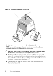
Be aware that the release lever can spring up suddenly if not firmly grasped. 9 Position your Hardware Owner's Manual for a system-specific illustration. See Figure 1-2. 4 Processor Installation Installing and Removing the Heat Sink 2 1 1 heat sink 2 release lever (2) NOTE: Your heat sink may appear differently ...
Be aware that the release lever can spring up suddenly if not firmly grasped. 9 Position your Hardware Owner's Manual for a system-specific illustration. See Figure 1-2. 4 Processor Installation Installing and Removing the Heat Sink 2 1 1 heat sink 2 release lever (2) NOTE: Your heat sink may appear differently ...
Information Update - Processor Installation
Page 9
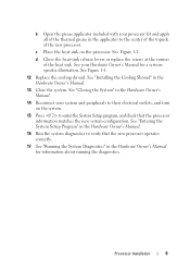
...the screws at the corners of the new processor. Processor Installation 9 See "Entering the System Setup Program" in the Hardware Owner's Manual. 16 Run the system diagnostics to verify that the processor information matches the new system configuration. See Figure 1-1. 12 Replace the cooling... shroud. See "Closing the System" in the Hardware Owner's Manual. 14 Reconnect your system and peripherals to their electrical outlets, and turn on the processor. b Open the grease applicator included with ...
...the screws at the corners of the new processor. Processor Installation 9 See "Entering the System Setup Program" in the Hardware Owner's Manual. 16 Run the system diagnostics to verify that the processor information matches the new system configuration. See Figure 1-1. 12 Replace the cooling... shroud. See "Closing the System" in the Hardware Owner's Manual. 14 Reconnect your system and peripherals to their electrical outlets, and turn on the processor. b Open the grease applicator included with ...
Getting Started Guide
Page 12
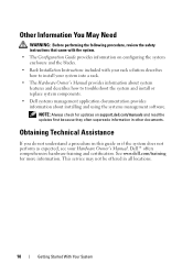
... the following procedure, review the safety instructions that came with the system. • The Configuration Guide provides information on support.dell.com/manuals and read the updates first because they often supersede information in all locations. 10 Getting Started With Your System NOTE: Always check... or if the system does not perform as expected, see your system into a rack. • The Hardware Owner's Manual provides information about system features and describes how to install your Hardware Owner's Manual. Dell™ offers comprehensive hardware training and certification.
... the following procedure, review the safety instructions that came with the system. • The Configuration Guide provides information on support.dell.com/manuals and read the updates first because they often supersede information in all locations. 10 Getting Started With Your System NOTE: Always check... or if the system does not perform as expected, see your system into a rack. • The Hardware Owner's Manual provides information about system features and describes how to install your Hardware Owner's Manual. Dell™ offers comprehensive hardware training and certification.

Getting Started Guide
Page 22
... per hour Storage 5% to 95% (noncondensing) Maximum vibration Operating 0.26 Grms at 10-350 Hz for 15 min Storage 1.54 Grms at support.dell.com/manuals. The system is not for use in the positive and negative x, y, and z axes (one pulse on each side of the system) of... 35,000 ft) 20 Getting Started With Your System I/O Module Specifications For information about environmental measurements for specific system configurations, see the Dell PowerEdge M1000e Systems Configuration Guide at 10-250 Hz for 15 min Maximum shock Operating One shock pulse in the positive z axis (one pulse...
... per hour Storage 5% to 95% (noncondensing) Maximum vibration Operating 0.26 Grms at 10-350 Hz for 15 min Storage 1.54 Grms at support.dell.com/manuals. The system is not for use in the positive and negative x, y, and z axes (one pulse on each side of the system) of... 35,000 ft) 20 Getting Started With Your System I/O Module Specifications For information about environmental measurements for specific system configurations, see the Dell PowerEdge M1000e Systems Configuration Guide at 10-250 Hz for 15 min Maximum shock Operating One shock pulse in the positive z axis (one pulse...
Dell PowerEdge M1000e Configuration Guide
Page 27
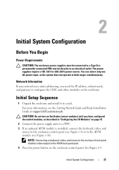
... System Configuration 27 Network Information If your network uses static addressing, you have configured the switch modules, as the system does not operate at support.dell.com/manuals. The power supplies require a 100-120 V or 200-240 V power source. For more information, see the Getting Started Guide and Rack Installation Guide at...
... System Configuration 27 Network Information If your network uses static addressing, you have configured the switch modules, as the system does not operate at support.dell.com/manuals. The power supplies require a 100-120 V or 200-240 V power source. For more information, see the Getting Started Guide and Rack Installation Guide at...

Dell PowerEdge M1000e Configuration Guide
Page 37
... is displayed. 5 In the Value field, type the path on page 31. 2 Click Chassis in . 2 Type: racadm fwupdate -g -u -a -d -m See the latest Dell Chassis Management Controller User's Guide at support.dell.com/manuals for complete instructions on how to the CMC Using the Web-Based Interface" on your management station or shared network where...
... is displayed. 5 In the Value field, type the path on page 31. 2 Click Chassis in . 2 Type: racadm fwupdate -g -u -a -d -m See the latest Dell Chassis Management Controller User's Guide at support.dell.com/manuals for complete instructions on how to the CMC Using the Web-Based Interface" on your management station or shared network where...
Dell PowerEdge M1000e Configuration Guide
Page 49
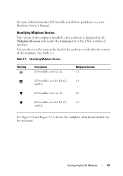
... the enclosure is displayed in the Midplane Revision field under the Summary tab of the midplane. Configuring the I /O module installation guidelines, see your Hardware Owner's Manual.
... the enclosure is displayed in the Midplane Revision field under the Summary tab of the midplane. Configuring the I /O module installation guidelines, see your Hardware Owner's Manual.

