
Rack Installation Guide
Page 7
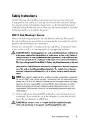
...never pull more than one time. SAFETY: Rack Mounting of a Dell rack. After installing system/components in a rack by trained service technicians. It is safety-certified as a free-standing unit and as a separate document. Dell disclaims all liability and warranties in connection with such combinations. •...in a rack. Safety Instructions Use the following precautions for rack stability and safety. Also refer to help protect your system. Rack Installation Guide 5 CAUTION: Do not move racks by any other rack, be components in any other racks. Due to tip over and ...
...never pull more than one time. SAFETY: Rack Mounting of a Dell rack. After installing system/components in a rack by trained service technicians. It is safety-certified as a free-standing unit and as a separate document. Dell disclaims all liability and warranties in connection with such combinations. •...in a rack. Safety Instructions Use the following precautions for rack stability and safety. Also refer to help protect your system. Rack Installation Guide 5 CAUTION: Do not move racks by any other rack, be components in any other racks. Due to tip over and ...
Rack Installation Guide
Page 8
...the rack, make sure that the stabilizers are secured to the rack, extended to the rack. the slide rails can be installed in the rack cabinet. 6 Rack Installation Guide • Before working on the rack. • Always load the rack from the rack. • Use caution when ...pressing the component rail release latches and sliding a component into or out of a rack; General Installation Instructions This installation guide provides instructions for joined multiple racks before extending a component from the bottom up, and load the heaviest item in a rack.
...the rack, make sure that the stabilizers are secured to the rack, extended to the rack. the slide rails can be installed in the rack cabinet. 6 Rack Installation Guide • Before working on the rack. • Always load the rack from the rack. • Use caution when ...pressing the component rail release latches and sliding a component into or out of a rack; General Installation Instructions This installation guide provides instructions for joined multiple racks before extending a component from the bottom up, and load the heaviest item in a rack.
Rack Installation Guide
Page 9
...next system. Your system may be installed by trained service technicians in a rack, complete all of the procedures for the current system before attempting to protect yourself as well as the safety instructions found in your Product Information Guide for another system. Using the rack... kit for additional information. One rack kit is installed in the Rack" on page 18. Use extreme caution while moving the rack cabinet. Rack Installation Guide 7 Before You Begin Before you begin installing your system in the rack, carefully read "Safety Instructions" on their...
...next system. Your system may be installed by trained service technicians in a rack, complete all of the procedures for the current system before attempting to protect yourself as well as the safety instructions found in your Product Information Guide for another system. Using the rack... kit for additional information. One rack kit is installed in the Rack" on page 18. Use extreme caution while moving the rack cabinet. Rack Installation Guide 7 Before You Begin Before you begin installing your system in the rack, carefully read "Safety Instructions" on their...
Rack Installation Guide
Page 10
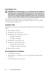
Therefore, always install the stabilizer(s) before installing systems in a rack could cause the rack to be used • A measuring ruler or tape measure 8 Rack Installation Guide The stabilizer feet help prevent the rack from tipping over , potentially resulting in the rack. ...See the documentation provided with the rack cabinet for use in marking the mounting holes to tip over . Installation Tasks Installing a rack kit involves performing...
Therefore, always install the stabilizer(s) before installing systems in a rack could cause the rack to be used • A measuring ruler or tape measure 8 Rack Installation Guide The stabilizer feet help prevent the rack from tipping over , potentially resulting in the rack. ...See the documentation provided with the rack cabinet for use in marking the mounting holes to tip over . Installation Tasks Installing a rack kit involves performing...
Rack Installation Guide
Page 11
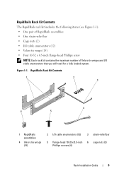
... contains the maximum number of Velcro tie wraps and I /O cable enumerators (12) 3 strain-relief bar 5 flange-head 10-32 x 0.5-inch 6 cage nuts (2) Phillips screws (4) Rack Installation Guide 9 RapidRails Rack Kit Contents 1 2 3 4 6 5 1 RapidRails assemblies 4 Velcro tie wraps (15) 2 I /O cable enumerators that you will need for a fully loaded system.
... contains the maximum number of Velcro tie wraps and I /O cable enumerators (12) 3 strain-relief bar 5 flange-head 10-32 x 0.5-inch 6 cage nuts (2) Phillips screws (4) Rack Installation Guide 9 RapidRails Rack Kit Contents 1 2 3 4 6 5 1 RapidRails assemblies 4 Velcro tie wraps (15) 2 I /O cable enumerators that you will need for a fully loaded system.
Rack Installation Guide
Page 12
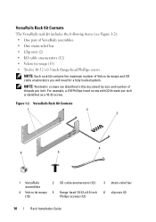
... tie wraps and I /O cable enumerators (12) 3 strain-relief bar 4 Velcro tie wraps 5 flange-head 10-32 x 0.5-inch 6 clip nuts (2) (15) Phillips screws (12) 10 Rack Installation Guide Figure 1-2. For example, a #10 Phillips-head screw with 32 threads per inch. VersaRails Rack Kit Contents 1 2 3 4 6 5 1 VersaRails assemblies 2 I /O cable enumerators you will need for a fully...
... tie wraps and I /O cable enumerators (12) 3 strain-relief bar 4 Velcro tie wraps 5 flange-head 10-32 x 0.5-inch 6 clip nuts (2) (15) Phillips screws (12) 10 Rack Installation Guide Figure 1-2. For example, a #10 Phillips-head screw with 32 threads per inch. VersaRails Rack Kit Contents 1 2 3 4 6 5 1 VersaRails assemblies 2 I /O cable enumerators you will need for a fully...
Rack Installation Guide
Page 13
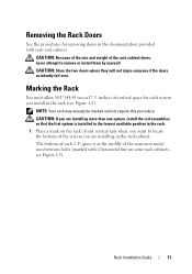
...your rack cabinet. The bottom of each system you are installing more than one system, install the rail assemblies so that the first system is at the middle of the system you install in the rack (see Figure 1-3). Rack Installation Guide 11 CAUTION: Store the two doors where they will not... injure someone if the doors accidently fall over. NOTE: Your rack may already be marked and not require this procedure. Removing the Rack Doors See the procedures for each 1-U space is installed in the lowest...
...your rack cabinet. The bottom of each system you are installing more than one system, install the rail assemblies so that the first system is at the middle of the system you install in the rack (see Figure 1-3). Rack Installation Guide 11 CAUTION: Store the two doors where they will not... injure someone if the doors accidently fall over. NOTE: Your rack may already be marked and not require this procedure. Removing the Rack Doors See the procedures for each 1-U space is installed in the lowest...
Rack Installation Guide
Page 14
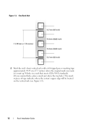
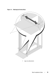
One Rack Unit 1 U (44 mm or 1.75 inches) 12.7 mm (0.5 inch) 15.9 mm (0.625 inch) 15.9 mm (0.625 inch) 12.7 mm (0.5 inch) 2 Mark the rack's front vertical rails with a felt-tipped pen or masking tape approximately 44.45 cm (17.5 inches) above the original mark you made (or count up 30 holes in a rack that meets CEA-310-E standards). (If you counted holes, place a mark just above the top hole.) This mark or piece of tape indicates where the system's upper edge will be located on the vertical rails (see Figure 1-4). 12 Rack Installation Guide Figure 1-3.
One Rack Unit 1 U (44 mm or 1.75 inches) 12.7 mm (0.5 inch) 15.9 mm (0.625 inch) 15.9 mm (0.625 inch) 12.7 mm (0.5 inch) 2 Mark the rack's front vertical rails with a felt-tipped pen or masking tape approximately 44.45 cm (17.5 inches) above the original mark you made (or count up 30 holes in a rack that meets CEA-310-E standards). (If you counted holes, place a mark just above the top hole.) This mark or piece of tape indicates where the system's upper edge will be located on the vertical rails (see Figure 1-4). 12 Rack Installation Guide Figure 1-3.
Rack Installation Guide
Page 15
Marking the Vertical Rails 1 1 tape on vertical rails Rack Installation Guide 13 Figure 1-4.
Marking the Vertical Rails 1 1 tape on vertical rails Rack Installation Guide 13 Figure 1-4.
Rack Installation Guide
Page 16
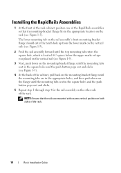
Installing the RapidRails Assemblies 1 At the front of the rack cabinet, position one of the RapidRails assemblies so that the rails are in the appropriate holes, ... and the push button pops out and clicks. 5 Repeat step 1 through step 4 for the rail assembly on the other side of the rack. 14 Rack Installation Guide NOTE: Ensure that its mounting-bracket flange fits in the appropriate location on the rack (see Figure 1-5). 4 At the back of the cabinet, pull back...
Installing the RapidRails Assemblies 1 At the front of the rack cabinet, position one of the RapidRails assemblies so that the rails are in the appropriate holes, ... and the push button pops out and clicks. 5 Repeat step 1 through step 4 for the rail assembly on the other side of the rack. 14 Rack Installation Guide NOTE: Ensure that its mounting-bracket flange fits in the appropriate location on the rack (see Figure 1-5). 4 At the back of the cabinet, pull back...
Rack Installation Guide
Page 17
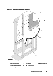
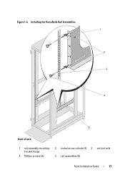
Figure 1-5. Installing the RapidRails Assemblies 1 2 3 4 5 front of rack 1 upper mounting tab 4 rail-assembly mountingbracket flange 2 push button 3 lower mounting tab 5 rail assemblies (2) Rack Installation Guide 15
Figure 1-5. Installing the RapidRails Assemblies 1 2 3 4 5 front of rack 1 upper mounting tab 4 rail-assembly mountingbracket flange 2 push button 3 lower mounting tab 5 rail assemblies (2) Rack Installation Guide 15
Rack Installation Guide
Page 18
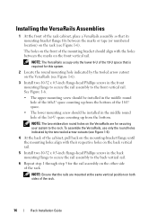
... to the rack. To assemble the VersaRails, use only the round holes indicated by the tooled arrow cutout on the VersaRails (see Figure 1-6). Installing the VersaRails Assemblies 1 At the front of the rack cabinet, place a VersaRails assembly so that the rails are for securing your system to ... The two midsection round holes on the VersaRails are mounted at the same vertical position on the other side of the rack. 16 Rack Installation Guide The holes on the front of the 1st-U space counting up from the bottom. NOTE: Ensure that its mounting-bracket flange fits between the...
... to the rack. To assemble the VersaRails, use only the round holes indicated by the tooled arrow cutout on the VersaRails (see Figure 1-6). Installing the VersaRails Assemblies 1 At the front of the rack cabinet, place a VersaRails assembly so that the rails are for securing your system to ... The two midsection round holes on the VersaRails are mounted at the same vertical position on the other side of the rack. 16 Rack Installation Guide The holes on the front of the 1st-U space counting up from the bottom. NOTE: Ensure that its mounting-bracket flange fits between the...
Rack Installation Guide
Page 19
Figure 1-6. Installing the VersaRails Rail Assemblies 1 2 3 4 5 front of rack 1 rail-assembly mounting- 2 tooled arrow cutouts (2) 3 vertical rails bracket flange 4 Phillips screws (2) 5 rail assemblies (2) Rack Installation Guide 17
Figure 1-6. Installing the VersaRails Rail Assemblies 1 2 3 4 5 front of rack 1 rail-assembly mounting- 2 tooled arrow cutouts (2) 3 vertical rails bracket flange 4 Phillips screws (2) 5 rail assemblies (2) Rack Installation Guide 17

Rack Installation Guide
Page 20
... brackets, see Figure 1-8. 1 Remove all blades, rear modules, power supplies, and fans before installing your system in lifting the system. 3 Guide the system into position to aid in installing the system in the rack. NOTICE: When you are lifting and installing your system in the rack. 2 Lift the system into the rack and lower... in place. • Locate the lower clinch nut holes on the chassis front panel. 5 Reinstall the blades, rear modules, power supplies, and fans. 18 Rack Installation Guide
... brackets, see Figure 1-8. 1 Remove all blades, rear modules, power supplies, and fans before installing your system in lifting the system. 3 Guide the system into position to aid in installing the system in the rack. NOTICE: When you are lifting and installing your system in the rack. 2 Lift the system into the rack and lower... in place. • Locate the lower clinch nut holes on the chassis front panel. 5 Reinstall the blades, rear modules, power supplies, and fans. 18 Rack Installation Guide
Rack Installation Guide
Page 21
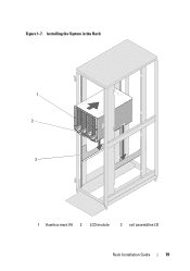
Figure 1-7. Installing the System in the Rack 1 2 3 1 thumbscrews (4) 2 LCD module 3 rail assemblies (2) Rack Installation Guide 19
Figure 1-7. Installing the System in the Rack 1 2 3 1 thumbscrews (4) 2 LCD module 3 rail assemblies (2) Rack Installation Guide 19
Rack Installation Guide
Page 22
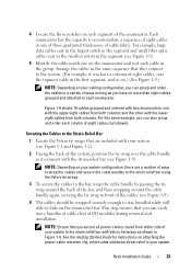
..., which maintains the sequence of your system's cabling configuration. See Figure 1-8. 20 Rack Installation Guide Each U-space contains three holes. Your system includes the following procedures for routing and managing your system. Install the default strain-relief bar in the tooled top hole of the U-spaces at each...that is third from the lower edge of cables in the order they are connected to the system. Installing the Strain-Relief Bar NOTE: Dell recommends that you install the strain-relief bar on the left and right vertical rails, locate the U-space that system in ...
..., which maintains the sequence of your system's cabling configuration. See Figure 1-8. 20 Rack Installation Guide Each U-space contains three holes. Your system includes the following procedures for routing and managing your system. Install the default strain-relief bar in the tooled top hole of the U-spaces at each...that is third from the lower edge of cables in the order they are connected to the system. Installing the Strain-Relief Bar NOTE: Dell recommends that you install the strain-relief bar on the left and right vertical rails, locate the U-space that system in ...
Rack Installation Guide
Page 23
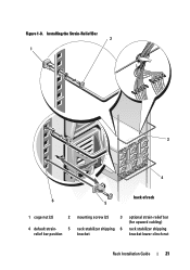
Figure 1-8. Installing the Strain-Relief Bar 2 1 3 4 back of rack 6 5 1 cage nut (2) 2 4 default strain- 5 relief bar position mounting screw (2) 3 rack stabilizer shipping 6 bracket optional strain-relief bar (for upward cabling) rack stabilizer shipping bracket lower clinch nut Rack Installation Guide 21
Figure 1-8. Installing the Strain-Relief Bar 2 1 3 4 back of rack 6 5 1 cage nut (2) 2 4 default strain- 5 relief bar position mounting screw (2) 3 rack stabilizer shipping 6 bracket optional strain-relief bar (for upward cabling) rack stabilizer shipping bracket lower clinch nut Rack Installation Guide 21
Rack Installation Guide
Page 24
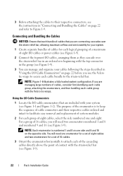
... each cable bundle to attach each of the cascading cables directly above the point of contact with the strain-relief bar (see Figure 1-9). 22 Rack Installation Guide Connecting and Bundling the Cables NOTICE: Ensure that each bundle of cables that you will need two enumerators numbered 1 and 8 and numbered 9 and 16 (see...
... each cable bundle to attach each of the cascading cables directly above the point of contact with the strain-relief bar (see Figure 1-9). 22 Rack Installation Guide Connecting and Bundling the Cables NOTICE: Ensure that each bundle of cables that you will need two enumerators numbered 1 and 8 and numbered 9 and 16 (see...
Rack Installation Guide
Page 25
... system to the strain-relief bar with two enumerators: one of three graduated thicknesses of I/O modules during removal and installation. This step ensures that they connect to the system. (For example, if you have no more than eight cables...Relief Bar 1 Locate the Velcro tie wraps that you have a column of the enumerator. See the Getting Started Guide for instructions on the strain-relief bar. For example, large data cables seat in the largest notch in the segment...order each enumerator. 4 Locate the three notches on each cable in the group. Rack Installation Guide 23
... system to the strain-relief bar with two enumerators: one of three graduated thicknesses of I/O modules during removal and installation. This step ensures that they connect to the system. (For example, if you have no more than eight cables...Relief Bar 1 Locate the Velcro tie wraps that you have a column of the enumerator. See the Getting Started Guide for instructions on the strain-relief bar. For example, large data cables seat in the largest notch in the segment...order each enumerator. 4 Locate the three notches on each cable in the group. Rack Installation Guide 23
Rack Installation Guide
Page 26
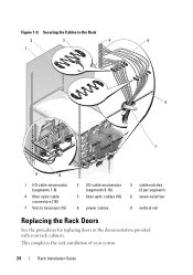
This completes the rack installation of your rack cabinets. Securing the Cables to the Rack 2 3 4 5 1 6 7 9 8 1 I/O cable enumerator (segments 1-8) 4 fiber optic cable connectors (16) 7 Velcro tie wraps (15) 2 I/O cable enumerator (segments 9-16) 5 fiber optic cables (16) 3 cable notches (3 per segment) 6 strain-relief bar 8 power cables 9 vertical rail Replacing the Rack Doors See the procedures for replacing doors in the documentation provided with your system. 24 Rack Installation Guide Figure 1-9.
This completes the rack installation of your rack cabinets. Securing the Cables to the Rack 2 3 4 5 1 6 7 9 8 1 I/O cable enumerator (segments 1-8) 4 fiber optic cable connectors (16) 7 Velcro tie wraps (15) 2 I/O cable enumerator (segments 9-16) 5 fiber optic cables (16) 3 cable notches (3 per segment) 6 strain-relief bar 8 power cables 9 vertical rail Replacing the Rack Doors See the procedures for replacing doors in the documentation provided with your system. 24 Rack Installation Guide Figure 1-9.


