
Getting Started Guide
Page 5
...V to five 3.5-inch hot-plug SAS hard drives. • An optional internal 1.44-MB, 3.5-inch diskette drive. • An optional internal slim-line optical drive. • An optional external USB diskette drive. • An optional external USB optical drive. • Two hot-pluggable, 1570...systems management. • An integrated VGA-compatible video subsystem based on the back panel), capable of supporting a diskette drive, an optical drive, a keyboard, a mouse, or a USB flash drive. • Systems management circuitry that monitors operation of 512-MB, 1-GB, 2-GB, or 4-GB memory modules ...
...V to five 3.5-inch hot-plug SAS hard drives. • An optional internal 1.44-MB, 3.5-inch diskette drive. • An optional internal slim-line optical drive. • An optional external USB diskette drive. • An optional external USB optical drive. • Two hot-pluggable, 1570...systems management. • An integrated VGA-compatible video subsystem based on the back panel), capable of supporting a diskette drive, an optical drive, a keyboard, a mouse, or a USB flash drive. • Systems management circuitry that monitors operation of 512-MB, 1-GB, 2-GB, or 4-GB memory modules ...

Getting Started Guide
Page 10
... Processor Processor type Expansion Bus Bus type Expansion slots Bandwidth Size Memory Architecture Memory module sockets Memory module capacities Minimum RAM Maximum RAM Drives Hard drives Optical drive Either two or four dual-core AMD Opteron™ 8000 Series processors PCIe Two x8 lane-width slots, six x4 lane-width ... processors) or 64 GB (four processors) (128 GB when 8 GB memory modules are available) Up to five 3.5-inch hot-plug SAS internal drives One optional slimline CD-ROM, DVD-ROM/CD-RW combination, or DVD-ROM NOTE: DVD devices are data only 8 Getting Started With Your System...
... Processor Processor type Expansion Bus Bus type Expansion slots Bandwidth Size Memory Architecture Memory module sockets Memory module capacities Minimum RAM Maximum RAM Drives Hard drives Optical drive Either two or four dual-core AMD Opteron™ 8000 Series processors PCIe Two x8 lane-width slots, six x4 lane-width ... processors) or 64 GB (four processors) (128 GB when 8 GB memory modules are available) Up to five 3.5-inch hot-plug SAS internal drives One optional slimline CD-ROM, DVD-ROM/CD-RW combination, or DVD-ROM NOTE: DVD devices are data only 8 Getting Started With Your System...

Hardware Owner's Manual (PDF)
Page 3
Contents 1 About Your System 9 Other Information You May Need 9 Accessing System Features During Startup 10 Front-Panel Features and Indicators 11 Hard-Drive Indicator Codes 13 Back-Panel Features and Indicators 14 Connecting External Devices 14 Power Indicator Codes 15 NIC Indicator Codes 16 LCD Status Messages 16 ...
Contents 1 About Your System 9 Other Information You May Need 9 Accessing System Features During Startup 10 Front-Panel Features and Indicators 11 Hard-Drive Indicator Codes 13 Back-Panel Features and Indicators 14 Connecting External Devices 14 Power Indicator Codes 15 NIC Indicator Codes 16 LCD Status Messages 16 ...

Hardware Owner's Manual (PDF)
Page 5
... 66 Installing a VRM 66 Removing a VRM 67 Installing a Diskette Drive 68 Installing an Optical Drive 70 Hard Drives 72 Before You Begin 72 Configuring the Boot Device 72 Removing a Drive Blank 73 Installing a Drive Blank 73 Removing a Hot-Plug Hard Drive 73 Installing a Hot-Plug Hard Drive 74 Replacing a Hard Drive in a Hard-Drive Carrier 75 SAS Controller Cards 76 Removing a SAS Controller Card...
... 66 Installing a VRM 66 Removing a VRM 67 Installing a Diskette Drive 68 Installing an Optical Drive 70 Hard Drives 72 Before You Begin 72 Configuring the Boot Device 72 Removing a Drive Blank 73 Installing a Drive Blank 73 Removing a Hot-Plug Hard Drive 73 Installing a Hot-Plug Hard Drive 74 Replacing a Hard Drive in a Hard-Drive Carrier 75 SAS Controller Cards 76 Removing a SAS Controller Card...

Hardware Owner's Manual (PDF)
Page 7
Troubleshooting an Optical Drive 109 Troubleshooting a Hard Drive 110 Troubleshooting a SAS Controller or SAS RAID Controller 111 Troubleshooting an External SAS Tape Drive 112 Troubleshooting Expansion Cards 113 Troubleshooting the Microprocessors 114 5 Running the System Diagnostics 117 Using Dell PowerEdge Diagnostics 117 System Diagnostics Features 117 When to Use the System Diagnostics 118 Running the System Diagnostics...
Troubleshooting an Optical Drive 109 Troubleshooting a Hard Drive 110 Troubleshooting a SAS Controller or SAS RAID Controller 111 Troubleshooting an External SAS Tape Drive 112 Troubleshooting Expansion Cards 113 Troubleshooting the Microprocessors 114 5 Running the System Diagnostics 117 Using Dell PowerEdge Diagnostics 117 System Diagnostics Features 117 When to Use the System Diagnostics 118 Running the System Diagnostics...

Hardware Owner's Manual (PDF)
Page 12
The LCD display lights amber when the system needs attention due to the system. 7 Hard drives (optional) 8 Optical drive and diskette drive (optional) NOTE: DVD devices are data only. Both the systems management software and the identification ... Connects USB 2.0-compliant devices to the system. 6 Video connector Connects a monitor to a problem with power supplies, fans, system temperature, or hard drives. Front-Panel LED Indicators, Buttons, and Connectors (continued) Item Indicator, Button, or Connector Icon 4 LCD display 5 USB connectors (2) Description ...
The LCD display lights amber when the system needs attention due to the system. 7 Hard drives (optional) 8 Optical drive and diskette drive (optional) NOTE: DVD devices are data only. Both the systems management software and the identification ... Connects USB 2.0-compliant devices to the system. 6 Video connector Connects a monitor to a problem with power supplies, fans, system temperature, or hard drives. Front-Panel LED Indicators, Buttons, and Connectors (continued) Item Indicator, Button, or Connector Icon 4 LCD display 5 USB connectors (2) Description ...

Hardware Owner's Manual (PDF)
Page 13
... Figure 1-2. See Figure 1-2. Hard-Drive Indicators 1 2 1 drive-status indicator (green 2 green drive-activity indicator and amber) Table 1-3 lists the drive indicator patterns for insertion or removal during this time. For example, if a hard drive fails, the "drive failed" pattern appears. After the replacement drive is applied. Hard-Drive Indicator Codes The hard-drive carriers have two indicators-a drive-activity indicator and a drive-status indicator. Different...
... Figure 1-2. See Figure 1-2. Hard-Drive Indicators 1 2 1 drive-status indicator (green 2 green drive-activity indicator and amber) Table 1-3 lists the drive indicator patterns for insertion or removal during this time. For example, if a hard drive fails, the "drive failed" pattern appears. After the replacement drive is applied. Hard-Drive Indicator Codes The hard-drive carriers have two indicators-a drive-activity indicator and a drive-status indicator. Different...

Hardware Owner's Manual (PDF)
Page 21
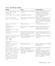
that there has been an error in the system, but is not configurable. See "Troubleshooting a Hard Drive" on page 56. See "RAC Card" on page 110. About Your System 21 LCD Status Messages (continued) Line 1 Message E1712...and reseat the PCI expansion cards. HDD ## Rbld Abrt Specified hard drive has ended See "Troubleshooting a Hard rebuild before completion. DRAC5 Conn2 Cbl DRAC 5 cable is faulty. HDD ## Removed Specified hard drive has been removed from the system. HDD ## Fault Specified hard drive has a fault. If the problem persists, the system board is...
that there has been an error in the system, but is not configurable. See "Troubleshooting a Hard Drive" on page 56. See "RAC Card" on page 110. About Your System 21 LCD Status Messages (continued) Line 1 Message E1712...and reseat the PCI expansion cards. HDD ## Rbld Abrt Specified hard drive has ended See "Troubleshooting a Hard rebuild before completion. DRAC5 Conn2 Cbl DRAC 5 cable is faulty. HDD ## Removed Specified hard drive has been removed from the system. HDD ## Fault Specified hard drive has a fault. If the problem persists, the system board is...

Hardware Owner's Manual (PDF)
Page 26
...message is required. No action is usually followed by keystroke. No boot device available Faulty or missing optical/diskette drive subsystem, hard drive, or harddrive subsystem, or no boot disk in manufacturing mode. System is unable to resolve the problem. Reboot ... Information only. Faulty keyboard controller; If the problem persists, see "Troubleshooting a Diskette Drive" on page 108, "Troubleshooting an Optical Drive" on page 109, and "Troubleshooting a Hard Drive" on page 31 for information about setting the order of manufacturing mode. Note the ...
...message is required. No action is usually followed by keystroke. No boot device available Faulty or missing optical/diskette drive subsystem, hard drive, or harddrive subsystem, or no boot disk in manufacturing mode. System is unable to resolve the problem. Reboot ... Information only. Faulty keyboard controller; If the problem persists, see "Troubleshooting a Diskette Drive" on page 108, "Troubleshooting an Optical Drive" on page 109, and "Troubleshooting a Hard Drive" on page 31 for information about setting the order of manufacturing mode. Note the ...

Hardware Owner's Manual (PDF)
Page 27
...ROM) Reseat the expansion cards. Install the NVRAM_CLR jumper and reboot the system. See Figure 6-1 for details. Table 1-8. Check the hard-drive configuration settings in the specified slot number. See "Using the System Setup Program" on page 53. If necessary, install the operating... system on your operating system documentation. See your hard drive. No timer tick interrupt Faulty system board. Use a bootable diskette. Reseat the PCIe card in initializing PCI device; See "Installing ...
...ROM) Reseat the expansion cards. Install the NVRAM_CLR jumper and reboot the system. See Figure 6-1 for details. Table 1-8. Check the hard-drive configuration settings in the specified slot number. See "Using the System Setup Program" on page 53. If necessary, install the operating... system on your operating system documentation. See your hard drive. No timer tick interrupt Faulty system board. Use a bootable diskette. Reseat the PCIe card in initializing PCI device; See "Installing ...

Hardware Owner's Manual (PDF)
Page 28
...the expansion cards. If the problem persists, see "Troubleshooting Expansion Cards" on page 56. See "Troubleshooting a Diskette Drive" on page 108 or "Troubleshooting a Hard Drive" on the disk, or the requested sector is installed in the correct expansion slot. Table 1-8. Ensure that the RAC... multi-bit errors were detected and replace the faulty memory module. See "Troubleshooting a Diskette Drive" on page 108, "Troubleshooting an Optical Drive" on page 109, or "Troubleshooting a Hard Drive" on page 106. RAC cables not connected, or RAC Check that the RAC cables are...
...the expansion cards. If the problem persists, see "Troubleshooting Expansion Cards" on page 56. See "Troubleshooting a Diskette Drive" on page 108 or "Troubleshooting a Hard Drive" on the disk, or the requested sector is installed in the correct expansion slot. Table 1-8. Ensure that the RAC... multi-bit errors were detected and replace the faulty memory module. See "Troubleshooting a Diskette Drive" on page 108, "Troubleshooting an Optical Drive" on page 109, or "Troubleshooting a Hard Drive" on page 106. RAC cables not connected, or RAC Check that the RAC cables are...
Hardware Owner's Manual (PDF)
Page 29
... memory modules are disabled: module(s) used by CPUn. Warning! Time-of -day clock stopped Faulty battery or faulty chip. See "Getting Help" on the boot hard drive. Unsupported CPU combination Unsupported CPU stepping detected Microprocessor(s) is reduced. Create a utility partition on page 129. Update the BIOS firmware. For more Faulty or improperly... memory configuration is not supported by Install a supported microprocessor or the system. Microprocessor(s) is not optimal. See "General Memory Module Installation Guidelines" on the boot hard drive. Table 1-8.
... memory modules are disabled: module(s) used by CPUn. Warning! Time-of -day clock stopped Faulty battery or faulty chip. See "Getting Help" on the boot hard drive. Unsupported CPU combination Unsupported CPU stepping detected Microprocessor(s) is reduced. Create a utility partition on page 129. Update the BIOS firmware. For more Faulty or improperly... memory configuration is not supported by Install a supported microprocessor or the system. Microprocessor(s) is not optimal. See "General Memory Module Installation Guidelines" on the boot hard drive. Table 1-8.

Hardware Owner's Manual (PDF)
Page 30
... messages include information, status, warning, and failure messages for obtaining technical assistance. See "Troubleshooting a Diskette Drive" on page 108, "Troubleshooting an Optical Drive" on page 109, or "Troubleshooting a Hard Drive" on selected drive Faulty diskette, optical/diskette drive assembly, hard drive, or hard-drive subsystem. Alert Messages Systems management software generates alert messages for your system. System Messages (continued) Message...
... messages include information, status, warning, and failure messages for obtaining technical assistance. See "Troubleshooting a Diskette Drive" on page 108, "Troubleshooting an Optical Drive" on page 109, or "Troubleshooting a Hard Drive" on selected drive Faulty diskette, optical/diskette drive assembly, hard drive, or hard-drive subsystem. Alert Messages Systems management software generates alert messages for your system. System Messages (continued) Message...

Hardware Owner's Manual (PDF)
Page 34
See support.dell.com for host systems that requires an IRQ. If this field is enabled and the system has failed to boot, the system will reattempt to ... (On default) Report Keyboard Errors (Report default) Description Determines the order in which the system searches for boot devices during POST. Hard disk allows the USB flash drive to act as a hard drive. Displays a screen to configure the front-panel LCD options and to each of the integrated devices on page 40 for a USB...
See support.dell.com for host systems that requires an IRQ. If this field is enabled and the system has failed to boot, the system will reattempt to ... (On default) Report Keyboard Errors (Report default) Description Determines the order in which the system searches for boot devices during POST. Hard disk allows the USB flash drive to act as a hard drive. Displays a screen to configure the front-panel LCD options and to each of the integrated devices on page 40 for a USB...

Hardware Owner's Manual (PDF)
Page 43
...; Cooling shrouds • Power supplies • Expansion cards • RAC card • System memory • Processors • Diskette drive • Optical drive • Hard drives • SAS controller card • RAID battery • External SAS tape drive • External Fibre Channel device • System battery • Control panel assembly • Fan interposer board • Power...
...; Cooling shrouds • Power supplies • Expansion cards • RAC card • System memory • Processors • Diskette drive • Optical drive • Hard drives • SAS controller card • RAID battery • External SAS tape drive • External Fibre Channel device • System battery • Control panel assembly • Fan interposer board • Power...

Hardware Owner's Manual (PDF)
Page 45
...9 1 fan modules (4) 4 memory modules (16) 7 optional RAC 8 2 SAS backplane 3 heatsink/processor (4) 5 expansion cards (7) 6 SAS controller card 8 optical slimline drive (optional) 9 optional 3.5-inch hard drives (5) The system board holds the system's control circuitry and other electronic components. Removing and Replacing the Optional Front Bezel 1 Unlock the keylock at the... the right end of the bezel and pull the bezel away from the system. The hard-drive bays provide space for up to a SAS controller card or an optional SAS RAID controller card through a SAS backplane. Figure...
...9 1 fan modules (4) 4 memory modules (16) 7 optional RAC 8 2 SAS backplane 3 heatsink/processor (4) 5 expansion cards (7) 6 SAS controller card 8 optical slimline drive (optional) 9 optional 3.5-inch hard drives (5) The system board holds the system's control circuitry and other electronic components. Removing and Replacing the Optional Front Bezel 1 Unlock the keylock at the... the right end of the bezel and pull the bezel away from the system. The hard-drive bays provide space for up to a SAS controller card or an optional SAS RAID controller card through a SAS backplane. Figure...

Hardware Owner's Manual (PDF)
Page 72
... card support hot-plug drive operation. Hard-Drive ID Numbers ID 0 ID 1 ID 2 ID 3 ID 4 Before You Begin NOTICE: Before you use only drives that you attempt to remove or install a drive while the system is configured correctly to five 3.5-inch SAS hard drives. When you plan to... partition and format the hard drives. See "SAS Backplane (Service-Only Procedure)" on page 31 for...
... card support hot-plug drive operation. Hard-Drive ID Numbers ID 0 ID 1 ID 2 ID 3 ID 4 Before You Begin NOTICE: Before you use only drives that you attempt to remove or install a drive while the system is configured correctly to five 3.5-inch SAS hard drives. When you plan to... partition and format the hard drives. See "SAS Backplane (Service-Only Procedure)" on page 31 for...

Hardware Owner's Manual (PDF)
Page 73
... the blank outward from the system and do not reinstall it, you do not replace the hard drive, insert a drive blank in the keyed side of the blank outward until it is powered down. Removing a Hot-Plug Hard Drive 1 Remove the bezel. See "Removing and Replacing the Optional Front Bezel" on page 73. See "Installing...
... the blank outward from the system and do not reinstall it, you do not replace the hard drive, insert a drive blank in the keyed side of the blank outward until it is powered down. Removing a Hot-Plug Hard Drive 1 Remove the bezel. See "Removing and Replacing the Optional Front Bezel" on page 73. See "Installing...

Hardware Owner's Manual (PDF)
Page 74
... Components See "Removing and Replacing the Optional Front Bezel" on page 73. 3 Install the hot-plug hard drive. Removing and Installing a Hot-Plug Hard Drive 1 2 3 1 hard drive 2 drive carrier 3 drive carrier release handle Installing a Hot-Plug Hard Drive NOTICE: When installing a hard drive, ensure that the adjacent drives are fully installed. Inserting a hard-drive carrier and attempting to lock its handle next to lock the...
... Components See "Removing and Replacing the Optional Front Bezel" on page 73. 3 Install the hot-plug hard drive. Removing and Installing a Hot-Plug Hard Drive 1 2 3 1 hard drive 2 drive carrier 3 drive carrier release handle Installing a Hot-Plug Hard Drive NOTICE: When installing a hard drive, ensure that the adjacent drives are fully installed. Inserting a hard-drive carrier and attempting to lock its handle next to lock the...

Hardware Owner's Manual (PDF)
Page 75
..., align the bottom rear screw hole on the hard-drive carrier and separate the hard drive from the slide rails on the hard drive with the connector end of the hard-drive carrier. 3 Attach the four screws to secure the hard drive to the hard-drive carrier. To install a new hard drive in a Hard-Drive Carrier To remove a hard drive from a drive carrier, remove the four screws from the...
..., align the bottom rear screw hole on the hard-drive carrier and separate the hard drive from the slide rails on the hard drive with the connector end of the hard-drive carrier. 3 Attach the four screws to secure the hard drive to the hard-drive carrier. To install a new hard drive in a Hard-Drive Carrier To remove a hard drive from a drive carrier, remove the four screws from the...


