
Hardware Owner's Manual (PDF)
Page 3
... Setup Program 31 Responding to Error Messages 31 Using the System Setup Program 31 System Setup Options 32 Main Screen 32 Memory Information Screen 35 CPU Information Screen 35 Integrated Devices Screen 36 System Security Screen 37 Exit Screen 38 Contents 3
... Setup Program 31 Responding to Error Messages 31 Using the System Setup Program 31 System Setup Options 32 Main Screen 32 Memory Information Screen 35 CPU Information Screen 35 Integrated Devices Screen 36 System Security Screen 37 Exit Screen 38 Contents 3

Hardware Owner's Manual (PDF)
Page 17
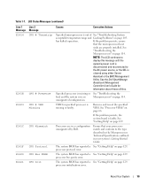
... N/A SYSTEM NAME E1000 E1A14 FAILSAFE, Call Support SAS Cable A E1A15 SAS Cable B E1114 Temp Ambient E1210 CMOS Batt E1211 ROMB Batt E12nn XX PwrGd E1229 CPU # VCORE E122A CPU # VTT Causes Corrective Actions A 62-character string that can change the system string in the System only. About Your System 17
... N/A SYSTEM NAME E1000 E1A14 FAILSAFE, Call Support SAS Cable A E1A15 SAS Cable B E1114 Temp Ambient E1210 CMOS Batt E1211 ROMB Batt E12nn XX PwrGd E1229 CPU # VCORE E122A CPU # VTT Causes Corrective Actions A 62-character string that can change the system string in the System only. About Your System 17

Hardware Owner's Manual (PDF)
Page 18
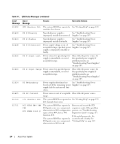
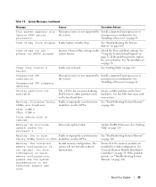
RPM of acceptable operating range. See "Troubleshooting System Cooling Problems" on support.dell.com for the most current system information. Cooling fan redundancy has been lost. E1410 CPU # IERR Specified microprocessor is See "Troubleshooting System out of specified cooling fan is ...129. LCD Status Messages (continued) Line 1 Message E122B E122C E122D E122E E1310 E1313 Line 2 Message 0.9V Over Voltage CPU Power Fault CPU # VDDIO CPU # VDDA RPM Fan ## Fan Redundancy Causes Corrective Actions 0.9 V regulator voltage has exceeded the allowable voltage range See "...
RPM of acceptable operating range. See "Troubleshooting System Cooling Problems" on support.dell.com for the most current system information. Cooling fan redundancy has been lost. E1410 CPU # IERR Specified microprocessor is See "Troubleshooting System out of specified cooling fan is ...129. LCD Status Messages (continued) Line 1 Message E122B E122C E122D E122E E1310 E1313 Line 2 Message 0.9V Over Voltage CPU Power Fault CPU # VDDIO CPU # VDDA RPM Fan ## Fan Redundancy Causes Corrective Actions 0.9 V regulator voltage has exceeded the allowable voltage range See "...
Hardware Owner's Manual (PDF)
Page 19
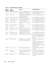
...page 129. NOTE: The LCD continues to display this message until the system's power cord is in a configuration unsupported by Dell. Ensure that the microprocessor heat sinks are in an Microprocessors" on page 105. processor protocol error. Remove and reseat the..." on page 114. unsupported configuration. Processors are properly installed. E1418 E1423 E141C E141F E1420 E1421 CPU # Presence CPU # VRM Missing CPU Mismatch CPU Protocol CPU Bus PERR CPU Init Specified processor is missing or See "Troubleshooting the bad, and the system is disconnected and ...
...page 129. NOTE: The LCD continues to display this message until the system's power cord is in a configuration unsupported by Dell. Ensure that the microprocessor heat sinks are in an Microprocessors" on page 105. processor protocol error. Remove and reseat the..." on page 114. unsupported configuration. Processors are properly installed. E1418 E1423 E141C E141F E1420 E1421 CPU # Presence CPU # VRM Missing CPU Mismatch CPU Protocol CPU Bus PERR CPU Init Specified processor is missing or See "Troubleshooting the bad, and the system is disconnected and ...
Hardware Owner's Manual (PDF)
Page 20
... been lost. range. Table 1-7. LCD Status Messages (continued) Line 1 Message E1422 E1610 E1614 E1618 E161C E1620 E1624 E1625 E1710 E1711 Line 2 Message Causes Corrective Actions CPU Machine Chk The system BIOS has reported a See "Getting Help" on page 105. machine check error. If the remaining power Supplies" on page 129. If...
... been lost. range. Table 1-7. LCD Status Messages (continued) Line 1 Message E1422 E1610 E1614 E1618 E161C E1620 E1624 E1625 E1710 E1711 Line 2 Message Causes Corrective Actions CPU Machine Chk The system BIOS has reported a See "Getting Help" on page 105. machine check error. If the remaining power Supplies" on page 129. If...
Hardware Owner's Manual (PDF)
Page 22
.... If problem persists, see "Getting Help" on page 129. See "Troubleshooting incorrect. SIO Err SIO failure. DRAC Config Dell remote access controller Check screen for specific error Memory population order messages. CPU Config CPU configuration failure. Int Controller Interrupt controller failure. Timer Fail Timer refresh failure. Shutdown Test BIOS shutdown test failure. Check...
.... If problem persists, see "Getting Help" on page 129. See "Troubleshooting incorrect. SIO Err SIO failure. DRAC Config Dell remote access controller Check screen for specific error Memory population order messages. CPU Config CPU configuration failure. Int Controller Interrupt controller failure. Timer Fail Timer refresh failure. Shutdown Test BIOS shutdown test failure. Check...
Hardware Owner's Manual (PDF)
Page 29
Time-of -day not set please run but no utility partition exists on the technical support web site. See "System Battery" on page 106. Unsupported CPU combination Unsupported CPU stepping detected Microprocessor(s) is not optimal. on page 78. See "General Memory Module Installation Guidelines" on page 64. microprocessor combination. If the problem persists...
Time-of -day not set please run but no utility partition exists on the technical support web site. See "System Battery" on page 106. Unsupported CPU combination Unsupported CPU stepping detected Microprocessor(s) is not optimal. on page 78. See "General Memory Module Installation Guidelines" on page 64. microprocessor combination. If the problem persists...

Hardware Owner's Manual (PDF)
Page 33
...Using the System Setup Program 33 NOTE: The System Setup program defaults are listed under their respective options, where applicable. Table 2-2. See "CPU Information Screen" on the system's internal calendar. Resets the date on page 35. Figure 2-1. NOTE: The options for the information fields ...that appear on page 37. System Setup Program Options Option System Time System Date Memory Information CPU Information Description Resets the time on the system configuration. Displays information related to microprocessors (speed, cache size, and so on page ...
...Using the System Setup Program 33 NOTE: The System Setup program defaults are listed under their respective options, where applicable. Table 2-2. See "CPU Information Screen" on the system's internal calendar. Resets the date on page 35. Figure 2-1. NOTE: The options for the information fields ...that appear on page 37. System Setup Program Options Option System Time System Date Memory Information CPU Information Description Resets the time on the system configuration. Displays information related to microprocessors (speed, cache size, and so on page ...

Hardware Owner's Manual (PDF)
Page 35
...Power Management (Disabled default) Processor X ID Description Specifies if the installed processor(s) support 64-bit extensions. when disabled, the CPU Performance State tables will be reported to Disabled. If this field is enabled, memory interleaving is supported if a symmetric memory ... memory speed. Displays the model number of system memory. See "General Memory Module Installation Guidelines" on the CPU Information screen. Table 2-3. When enabled, the CPU Performance State tables will not be reported to disabled (the default), the system can support Non-Uniform Memory...
...Power Management (Disabled default) Processor X ID Description Specifies if the installed processor(s) support 64-bit extensions. when disabled, the CPU Performance State tables will be reported to Disabled. If this field is enabled, memory interleaving is supported if a symmetric memory ... memory speed. Displays the model number of system memory. See "General Memory Module Installation Guidelines" on the CPU Information screen. Table 2-3. When enabled, the CPU Performance State tables will not be reported to disabled (the default), the system can support Non-Uniform Memory...
Hardware Owner's Manual (PDF)
Page 36
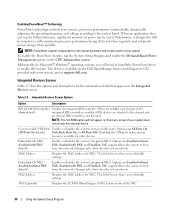
...the MAC address for other devices. PXE support allows the system to the channel and an external IDE controller is available on the CPU Information screen. TOE Capability Displays the TCP-IP Offload Engine (TOE) feature status of the (Auto default) integrated IDE controller ... Options Option Description IDE CD-ROM Controller Enables the integrated IDE controller. PXE support allows the system to the task at support.dell.com. MAC Address Displays the MAC address for the information fields that appear on your system's processor performance automatically, dynamically adjusting the...
...the MAC address for other devices. PXE support allows the system to the channel and an external IDE controller is available on the CPU Information screen. TOE Capability Displays the TCP-IP Offload Engine (TOE) feature status of the (Auto default) integrated IDE controller ... Options Option Description IDE CD-ROM Controller Enables the integrated IDE controller. PXE support allows the system to the task at support.dell.com. MAC Address Displays the MAC address for the information fields that appear on your system's processor performance automatically, dynamically adjusting the...

Hardware Owner's Manual (PDF)
Page 59
... 4 GB 6 GB 8 GB 8 GB 16 GB 16 GB 24 GB 32 GB DIMM1 512 MB 512 MB 1 GB 1 GB 1 GB 2 GB 2 GB 4 GB 4 GB 4 GB CPU 1 DIMM2 DIMM3 512 MB 512 MB 1 GB 1 GB 1 GB 2 GB 2 GB 4 GB 4 GB 4 GB 512 MB 512 MB 1 GB 2 GB 2 GB 4 GB DIMM4 512 MB...
... 4 GB 6 GB 8 GB 8 GB 16 GB 16 GB 24 GB 32 GB DIMM1 512 MB 512 MB 1 GB 1 GB 1 GB 2 GB 2 GB 4 GB 4 GB 4 GB CPU 1 DIMM2 DIMM3 512 MB 512 MB 1 GB 1 GB 1 GB 2 GB 2 GB 4 GB 4 GB 4 GB 512 MB 512 MB 1 GB 2 GB 2 GB 4 GB DIMM4 512 MB...

Hardware Owner's Manual (PDF)
Page 125
...RAC_CONN remote access card (RAC) connector 12 RAC_CONN1 Connector for the 40-pin RAC cable 13 RAC_CONN2 Connector for the 50-pin RAC cable 14 CPU 1 Processor 1 connector 15 DIMM 1 Memory module connector, slot 1 16 DIMM 2 Memory module connector, slot 2 17 DIMM 3 Memory module...23 12V 12 V power connector 24 PWR_3.3Stby_Cntrl Power distribution board signal connector 25 CPU 3 Processor 3 connector 26 VRM 3 Voltage regulator module (VRM) 3 connector 27 VRM 4 VRM 4 connector 28 CPU 4 Processor 4 connector 29 INTRUSION Intrusion switch connector NOTE: For the full name ...
...RAC_CONN remote access card (RAC) connector 12 RAC_CONN1 Connector for the 40-pin RAC cable 13 RAC_CONN2 Connector for the 50-pin RAC cable 14 CPU 1 Processor 1 connector 15 DIMM 1 Memory module connector, slot 1 16 DIMM 2 Memory module connector, slot 2 17 DIMM 3 Memory module...23 12V 12 V power connector 24 PWR_3.3Stby_Cntrl Power distribution board signal connector 25 CPU 3 Processor 3 connector 26 VRM 3 Voltage regulator module (VRM) 3 connector 27 VRM 4 VRM 4 connector 28 CPU 4 Processor 4 connector 29 INTRUSION Intrusion switch connector NOTE: For the full name ...

Hardware Owner's Manual (PDF)
Page 126
... 31 DIMM 14 Memory module connector, slot 14 32 DIMM 15 Memory module connector, slot 15 33 DIMM 16 Memory module connector, slot 16 34 CPU 2 Processor 2 connector 35 DIMM 5 Memory module connector, slot 5 36 DIMM 6 Memory module connector, slot 6 37 DIMM 7 Memory module connector, slot 7 38 DIMM 8 Memory module connector...
... 31 DIMM 14 Memory module connector, slot 14 32 DIMM 15 Memory module connector, slot 15 33 DIMM 16 Memory module connector, slot 16 34 CPU 2 Processor 2 connector 35 DIMM 5 Memory module connector, slot 5 36 DIMM 6 Memory module connector, slot 6 37 DIMM 7 Memory module connector, slot 7 38 DIMM 8 Memory module connector...

Hardware Owner's Manual (PDF)
Page 156
...server management. Your system contains an expansion bus that branch off them. The device names for the serial ports on the system board. CPU - DC - DHCP - A comprehensive set of automatically assigning an IP address to the system by collecting information about the system's ... names, such as NICs. coprocessor - A method of specific processing tasks. CD - A math coprocessor, for peripherals, such as www.dell.com, into an expansion-card connector on your system. See processor. See also memory module. Conventional memory is usually made up entirely of...
...server management. Your system contains an expansion bus that branch off them. The device names for the serial ports on the system board. CPU - DC - DHCP - A comprehensive set of automatically assigning an IP address to the system by collecting information about the system's ... names, such as NICs. coprocessor - A method of specific processing tasks. CD - A math coprocessor, for peripherals, such as www.dell.com, into an expansion-card connector on your system. See processor. See also memory module. Conventional memory is usually made up entirely of...

Hardware Owner's Manual (PDF)
Page 159
... servers and storage systems in the Windows 2000 operating system. A method of independent disks. readme file - partition - PGA - processor - Redundant array of providing data redundancy. CPU is lost when you turn off your system's boot routine and the POST. Pin grid array. Personal System/2. ROMB - Preboot eXecution Environment. NTFS - The NT...
... servers and storage systems in the Windows 2000 operating system. A method of independent disks. readme file - partition - PGA - processor - Redundant array of providing data redundancy. CPU is lost when you turn off your system's boot routine and the POST. Pin grid array. Personal System/2. ROMB - Preboot eXecution Environment. NTFS - The NT...
Installation Instructions AMD™ Opteron™ 2000 and 8000 Series Processors
Page 2
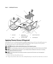
... you take all necessary precautions to apply thermal grease. NOTE: See "Installing System Components" in your processor kit, perform the following procedure to prevent the CPU socket cover from popping off the processor. 1 Remove the heat sink and the processor. 2 Using a clean, lint-free cloth, remove the existing thermal grease from...
... you take all necessary precautions to apply thermal grease. NOTE: See "Installing System Components" in your processor kit, perform the following procedure to prevent the CPU socket cover from popping off the processor. 1 Remove the heat sink and the processor. 2 Using a clean, lint-free cloth, remove the existing thermal grease from...


