
Getting Started Guide
Page 7
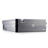
Getting Started With Your System 5 This section describes the steps to set up your system and identify each item.(Your system may not include the optional rack kit and bezel shown here.) Keep all shipping materials in your Product Information Guide. Unpacking the System Unpack your system for the first time. Installation and Configuration CAUTION: Before performing the following procedure, read and follow the safety instructions and important regulatory information in case you need them later.
Getting Started With Your System 5 This section describes the steps to set up your system and identify each item.(Your system may not include the optional rack kit and bezel shown here.) Keep all shipping materials in your Product Information Guide. Unpacking the System Unpack your system for the first time. Installation and Configuration CAUTION: Before performing the following procedure, read and follow the safety instructions and important regulatory information in case you need them later.

Getting Started Guide
Page 9
... Started With Your System 7 Connect the system's power cables to the monitor (optional). The power indicators should light. If you have purchased the optional system bezel, install it after turning on the system and the monitor (optional). Turning on the System and Monitor Press the power button on the system. Plug...
... Started With Your System 7 Connect the system's power cables to the monitor (optional). The power indicators should light. If you have purchased the optional system bezel, install it after turning on the system and the monitor (optional). Turning on the System and Monitor Press the power button on the system. Plug...

Hardware Owner's Manual (PDF)
Page 4
... Setup Module 42 BMC Setup Module Options 42 3 Installing System Components 43 Recommended Tools 44 Inside the System 44 Removing and Replacing the Optional Front Bezel 45 Opening and Closing the System 46 Opening the System 46 Closing the System 47 Cooling Fans 48 Removing a Cooling Fan 48 Replacing a Cooling Fan...
... Setup Module 42 BMC Setup Module Options 42 3 Installing System Components 43 Recommended Tools 44 Inside the System 44 Removing and Replacing the Optional Front Bezel 45 Opening and Closing the System 46 Opening the System 46 Closing the System 47 Cooling Fans 48 Removing a Cooling Fan 48 Replacing a Cooling Fan...

Hardware Owner's Manual (PDF)
Page 11
... a particular system within a rack. About Your System 11 Front-Panel Features and Indicators Figure 1-1 shows the controls, indicators, and connectors located behind the optional rack bezel on indicator, power button 2 NMI button 3 System identification button Description The power button controls the DC power supply output to do so by qualified support...
... a particular system within a rack. About Your System 11 Front-Panel Features and Indicators Figure 1-1 shows the controls, indicators, and connectors located behind the optional rack bezel on indicator, power button 2 NMI button 3 System identification button Description The power button controls the DC power supply output to do so by qualified support...

Hardware Owner's Manual (PDF)
Page 43
Installing System Components This section describes how to install the following system components: • Front bezel • System cover • Cooling fan modules • Cooling shrouds • Power supplies • Expansion cards • RAC card • System memory • Processors • ...
Installing System Components This section describes how to install the following system components: • Front bezel • System cover • Cooling fan modules • Cooling shrouds • Power supplies • Expansion cards • RAC card • System memory • Processors • ...

Hardware Owner's Manual (PDF)
Page 44
... shrouds if the system is turned on. See your Product Information Guide for complete information about safety precautions, working inside the system. In Figure 3-1, the bezel, system cover, and cooling shrouds are authorized to remove the system cover and access any of the system. Recommended Tools You may need the following...
... shrouds if the system is turned on. See your Product Information Guide for complete information about safety precautions, working inside the system. In Figure 3-1, the bezel, system cover, and cooling shrouds are authorized to remove the system cover and access any of the system. Recommended Tools You may need the following...

Hardware Owner's Manual (PDF)
Page 45
Removing and Replacing the Optional Front Bezel 1 Unlock the keylock at the left end of the bezel. 2 Rotate the left end of the bezel away from the front panel. 3 Unhook the right end of the bezel and pull the bezel away from the system. Inside the System 4 3 2 1 5 6 7 9 1 fan modules (4) 4 memory modules (16) 7 optional RAC 8 2 SAS backplane...
Removing and Replacing the Optional Front Bezel 1 Unlock the keylock at the left end of the bezel. 2 Rotate the left end of the bezel away from the front panel. 3 Unhook the right end of the bezel and pull the bezel away from the system. Inside the System 4 3 2 1 5 6 7 9 1 fan modules (4) 4 memory modules (16) 7 optional RAC 8 2 SAS backplane...

Hardware Owner's Manual (PDF)
Page 46
... cover on both sides and carefully lift the cover away from the electrical outlet and peripherals. 2 Rotate the latch release lock on top of the bezel onto the system. See Figure 3-2. See Figure 3-3. 3 Lift up on the latch on the latch in a counter clockwise direction to remove the ...inside the system. To avoid injury, do not attempt to assist you. Removing and Replacing the Optional Front Bezel 1 2 1 key lock 2 bezel To replace the optional bezel, hook the right end of the bezel onto the chassis, then fit the free end of the system and slide the cover back. Opening and ...
... cover on both sides and carefully lift the cover away from the electrical outlet and peripherals. 2 Rotate the latch release lock on top of the bezel onto the system. See Figure 3-2. See Figure 3-3. 3 Lift up on the latch on the latch in a counter clockwise direction to remove the ...inside the system. To avoid injury, do not attempt to assist you. Removing and Replacing the Optional Front Bezel 1 2 1 key lock 2 bezel To replace the optional bezel, hook the right end of the bezel onto the chassis, then fit the free end of the system and slide the cover back. Opening and ...

Hardware Owner's Manual (PDF)
Page 68
c Lift the optical drive or optical drive filler plate from the electrical outlet. 2 Remove the front bezel, if attached. See Figure 3-14. Removing and Installing the Diskette/Optical Drive Carrier 2 1 1 release latch 2 diskette/optical drive carrier 4 Remove the optical drive or optical .... 3 To remove the drive carrier, pull the release latch forward, then slide the carrier out of the socket. See"Removing and Replacing the Optional Front Bezel" on page 49. 4 Locate the VRM sockets.
c Lift the optical drive or optical drive filler plate from the electrical outlet. 2 Remove the front bezel, if attached. See Figure 3-14. Removing and Installing the Diskette/Optical Drive Carrier 2 1 1 release latch 2 diskette/optical drive carrier 4 Remove the optical drive or optical .... 3 To remove the drive carrier, pull the release latch forward, then slide the carrier out of the socket. See"Removing and Replacing the Optional Front Bezel" on page 49. 4 Locate the VRM sockets.

Hardware Owner's Manual (PDF)
Page 70
... spring slightly away from the filler plate, then lift the filler plate from its electrical outlet. 2 Remove the bezel. See "Removing and Replacing the Optional Front Bezel" on the carrier fit into the front panel and connects to their electrical outlets. Installing an Optical Drive The optional...filler plate from the latch securing the optical drive or filler plate. See Figure 3-15 10 Replace the front bezel, if applicable. See "Removing and Replacing the Optional Front Bezel" on page 45. 3 To remove the drive carrier, pull the release latch forward, then slide the carrier...
... spring slightly away from the filler plate, then lift the filler plate from its electrical outlet. 2 Remove the bezel. See "Removing and Replacing the Optional Front Bezel" on the carrier fit into the front panel and connects to their electrical outlets. Installing an Optical Drive The optional...filler plate from the latch securing the optical drive or filler plate. See Figure 3-15 10 Replace the front bezel, if applicable. See "Removing and Replacing the Optional Front Bezel" on page 45. 3 To remove the drive carrier, pull the release latch forward, then slide the carrier...

Hardware Owner's Manual (PDF)
Page 71
.... 6 Attach the interface board to their electrical outlets. Installing System Components 71 See "Removing and Replacing the Optional Front Bezel" on the carrier fit into place. See Figure 3-14 9 Replace the front bezel, if applicable. See Figure 3-16. 7 Reinstall the latch and tighten the thumbscrew. 8 Slide in the drive carrier until the...
.... 6 Attach the interface board to their electrical outlets. Installing System Components 71 See "Removing and Replacing the Optional Front Bezel" on the carrier fit into place. See Figure 3-14 9 Replace the front bezel, if applicable. See Figure 3-16. 7 Reinstall the latch and tighten the thumbscrew. 8 Slide in the drive carrier until the...

Hardware Owner's Manual (PDF)
Page 73
...a 3.5-inch drive blank, insert and rotate in the keyed side of the blank into the drive bay. See "Removing and Replacing the Optional Front Bezel" on page 45. 2 From the RAID management software, prepare the drive for information about hot-plug drive removal. If the drive has been online...carrier signal that the drive can be removed safely. Installing System Components 73 Removing a Hot-Plug Hard Drive 1 Remove the bezel. See "Removing and Replacing the Optional Front Bezel" on the latch to eject the blank outward from the system and do not replace the hard drive, insert a drive ...
...a 3.5-inch drive blank, insert and rotate in the keyed side of the blank into the drive bay. See "Removing and Replacing the Optional Front Bezel" on page 45. 2 From the RAID management software, prepare the drive for information about hot-plug drive removal. If the drive has been online...carrier signal that the drive can be removed safely. Installing System Components 73 Removing a Hot-Plug Hard Drive 1 Remove the bezel. See "Removing and Replacing the Optional Front Bezel" on the latch to eject the blank outward from the system and do not replace the hard drive, insert a drive ...

Hardware Owner's Manual (PDF)
Page 74
... When installing a hard drive, ensure that the adjacent drives are fully installed. See the documentation supplied with your operating system. 1 Remove the bezel. See "Removing a Drive Blank" on the hard-drive carrier. c Close the handle to a partially installed carrier can damage the partially installed... carrier's shield spring and make it . Figure 3-18. See "Removing and Replacing the Optional Front Bezel" on page 45. 74 Installing System Components b Insert the hard-drive carrier into the drive bay until the carrier contacts the backplane....
... When installing a hard drive, ensure that the adjacent drives are fully installed. See the documentation supplied with your operating system. 1 Remove the bezel. See "Removing a Drive Blank" on the hard-drive carrier. c Close the handle to a partially installed carrier can damage the partially installed... carrier's shield spring and make it . Figure 3-18. See "Removing and Replacing the Optional Front Bezel" on page 45. 74 Installing System Components b Insert the hard-drive carrier into the drive bay until the carrier contacts the backplane....

Hardware Owner's Manual (PDF)
Page 82
... drive carrier from the electrical outlet. 2 Open the system. See "Removing a Cooling Fan" on page 47. 7 Replace the front bezel, if applicable. See Figure 3-23. 82 Installing System Components See your Product Information Guide for complete information about safety precautions, working inside the...interposer board is being replaced). See "Opening the System" on the system and attached peripherals. See "Removing and Replacing the Optional Front Bezel" on page 45. 8 Reconnect the system to remove the system cover and access any of the chassis. Fan Interposer Board (Service-...
... drive carrier from the electrical outlet. 2 Open the system. See "Removing a Cooling Fan" on page 47. 7 Replace the front bezel, if applicable. See Figure 3-23. 82 Installing System Components See your Product Information Guide for complete information about safety precautions, working inside the...interposer board is being replaced). See "Opening the System" on the system and attached peripherals. See "Removing and Replacing the Optional Front Bezel" on page 45. 8 Reconnect the system to remove the system cover and access any of the chassis. Fan Interposer Board (Service-...

Hardware Owner's Manual (PDF)
Page 87
...and attached peripherals, and disconnect the system from the control-panel cable connector on page 49. See "Removing and Replacing the Optional Front Bezel" on page 62. 4 Replace the top cooling shroud. See "Removing the Cooling Shrouds" on the front of the SAS backplane. ...remove the system cover and access any of the components inside the computer, and protecting against electrostatic discharge. 1 If applicable, remove the bezel. See "Opening the System" on , including any attached peripherals. NOTICE: To prevent damage to the drives and backplane, you can replace...
...and attached peripherals, and disconnect the system from the control-panel cable connector on page 49. See "Removing and Replacing the Optional Front Bezel" on page 62. 4 Replace the top cooling shroud. See "Removing the Cooling Shrouds" on the front of the SAS backplane. ...remove the system cover and access any of the components inside the computer, and protecting against electrostatic discharge. 1 If applicable, remove the bezel. See "Opening the System" on , including any attached peripherals. NOTICE: To prevent damage to the drives and backplane, you can replace...

Hardware Owner's Manual (PDF)
Page 95
See "Removing and Replacing the Optional Front Bezel" on page 74. 15 Close the system. See "Installing a Hot-Plug Hard Drive" on page 45. Installing System Components 95 14 Install the SAS hard drives in their original locations. See "Closing the System" on page 47. 16 Reconnect the system to its electrical outlet and turn the system on, including any attached peripherals. 17 Replace the bezel.
See "Removing and Replacing the Optional Front Bezel" on page 74. 15 Close the system. See "Installing a Hot-Plug Hard Drive" on page 45. Installing System Components 95 14 Install the SAS hard drives in their original locations. See "Closing the System" on page 47. 16 Reconnect the system to its electrical outlet and turn the system on, including any attached peripherals. 17 Replace the bezel.

Hardware Owner's Manual (PDF)
Page 108
See "Using Dell PowerEdge Diagnostics" on page 55. 8 Close the system. If the tests ... installed. If it is securely attached. See "Opening and Closing the System" on page 31. 2 Remove the bezel. Troubleshooting a Diskette Drive Problem • Error message indicates a diskette drive problem. Before performing any procedure, see whether... modules have been checked, see whether the diskette drive works correctly. See "Removing and Replacing the Optional Front Bezel" on page 129. 11 Turn off the system and attached peripherals, and disconnect the system from the electrical ...
See "Using Dell PowerEdge Diagnostics" on page 55. 8 Close the system. If the tests ... installed. If it is securely attached. See "Opening and Closing the System" on page 31. 2 Remove the bezel. Troubleshooting a Diskette Drive Problem • Error message indicates a diskette drive problem. Before performing any procedure, see whether... modules have been checked, see whether the diskette drive works correctly. See "Removing and Replacing the Optional Front Bezel" on page 129. 11 Turn off the system and attached peripherals, and disconnect the system from the electrical ...

Hardware Owner's Manual (PDF)
Page 109
... an Optical Drive Problem • System cannot read data from the electrical outlet. 5 Open or remove the bezel. See "Removing and Replacing the Optional Front Bezel" on page 53. 14 Close the system. See "Using Dell PowerEdge Diagnostics" on page 46. 9 Reconnect the system to the sideplane. 8 Close the system. If the problem is...
... an Optical Drive Problem • System cannot read data from the electrical outlet. 5 Open or remove the bezel. See "Removing and Replacing the Optional Front Bezel" on page 53. 14 Close the system. See "Using Dell PowerEdge Diagnostics" on page 46. 9 Reconnect the system to the sideplane. 8 Close the system. If the problem is...

Hardware Owner's Manual (PDF)
Page 110
... the computer, and protecting against electrostatic discharge. Depending on the hard drive. See "Removing and Replacing the Optional Front Bezel" on page 117. See "Using Dell PowerEdge Diagnostics" on page 45. 3 If you proceed, back up all files on page 129. See the operating system... documentation for your system has a SAS RAID controller card, perform the following steps. 2 Remove the bezel. Action CAUTION: Only trained ...
... the computer, and protecting against electrostatic discharge. Depending on the hard drive. See "Removing and Replacing the Optional Front Bezel" on page 117. See "Using Dell PowerEdge Diagnostics" on page 45. 3 If you proceed, back up all files on page 129. See the operating system... documentation for your system has a SAS RAID controller card, perform the following steps. 2 Remove the bezel. Action CAUTION: Only trained ...

Hardware Owner's Manual (PDF)
Page 163
... 80 cooling fan removing, 48 replacing, 49 troubleshooting, 106 cooling shroud removing, 49 replacing, 50 cover closing, 47 opening, 46 D Dell contacting, 133-134 diagnostic messages, 30 diagnostics advanced testing options, 118 testing options, 118 when to use, 118 DIMMs See memory modules (...DIMMs). battery (RAID) installing, 76 troubleshooting, 111 battery (system) replacing, 78 troubleshooting, 104 bezel removing, 45 BMC configuration, 41 setup module, 10 boot device configuring, 72 C CD/DVD drive See optical drive. diskette drive drive carrier,...
... 80 cooling fan removing, 48 replacing, 49 troubleshooting, 106 cooling shroud removing, 49 replacing, 50 cover closing, 47 opening, 46 D Dell contacting, 133-134 diagnostic messages, 30 diagnostics advanced testing options, 118 testing options, 118 when to use, 118 DIMMs See memory modules (...DIMMs). battery (RAID) installing, 76 troubleshooting, 111 battery (system) replacing, 78 troubleshooting, 104 bezel removing, 45 BMC configuration, 41 setup module, 10 boot device configuring, 72 C CD/DVD drive See optical drive. diskette drive drive carrier,...


