Installing the DRAC 4/P (.pdf)
Page 1
... chip, carefully rotate the heat sink in a clockwise, then counterclockwise, direction until it releases from the retention-clip securing slots, and then lift up the retention clip. March 2005 www.dell.com | support.dell.com About Cautions CAUTION: A CAUTION indicates a potential for instructions on how to remove and replace the system board. NOTE...: See the latest version of the chip. 3 Lift off the heat sink. Do not pry the heat sink off of the system's documentation on support.dell.com for property damage, personal injury, or death.
... chip, carefully rotate the heat sink in a clockwise, then counterclockwise, direction until it releases from the retention-clip securing slots, and then lift up the retention clip. March 2005 www.dell.com | support.dell.com About Cautions CAUTION: A CAUTION indicates a potential for instructions on how to remove and replace the system board. NOTE...: See the latest version of the chip. 3 Lift off the heat sink. Do not pry the heat sink off of the system's documentation on support.dell.com for property damage, personal injury, or death.
Installing the DRAC 4/P (.pdf)
Page 2
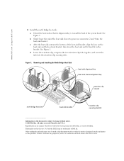
...permission of Dell Inc. b Slowly lower the end of Dell Inc. See Figure 1. Removing and Installing the North Bridge Heat Sink heat-sink alignment key heat-sink bracket alignment key retention-clip tabs (2) north bridge heat sink heat-sink bracket retention-clip securing slots (2) ...lays flat in the bracket. Reproduction in any proprietary interest in the U.S.A. disclaims any manner whatsoever without notice. © 2005 Dell Inc. See Figure 1. d Lower the retention clip, compress the two retention-clip tabs together, and secure the tabs into the heat...
...permission of Dell Inc. b Slowly lower the end of Dell Inc. See Figure 1. Removing and Installing the North Bridge Heat Sink heat-sink alignment key heat-sink bracket alignment key retention-clip tabs (2) north bridge heat sink heat-sink bracket retention-clip securing slots (2) ...lays flat in the bracket. Reproduction in any proprietary interest in the U.S.A. disclaims any manner whatsoever without notice. © 2005 Dell Inc. See Figure 1. d Lower the retention clip, compress the two retention-clip tabs together, and secure the tabs into the heat...
Installation and Troubleshooting Guide (.htm)
Page 19
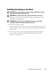
... than one component out of the rack at a time. 1 Pull the two interior slide assemblies out of the rack until they lock in the rack. Dell™ Rack Installation Guide 17 Using a minimum of two persons, each person should place one hand on the front-bottom of the system and the... first system in the lowest available position in the fully extended position. CAUTION: Because of the size and weight of the system with the back slots on the sides of the system, never attempt to install the system in the slide assemblies by yourself. 2 Lift the system into position.
... than one component out of the rack at a time. 1 Pull the two interior slide assemblies out of the rack until they lock in the rack. Dell™ Rack Installation Guide 17 Using a minimum of two persons, each person should place one hand on the front-bottom of the system and the... first system in the lowest available position in the fully extended position. CAUTION: Because of the size and weight of the system with the back slots on the sides of the system, never attempt to install the system in the slide assemblies by yourself. 2 Lift the system into position.
Installation and Troubleshooting Guide (.htm)
Page 20
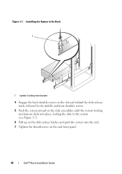
Installing the System in the Rack 1 1 system locking mechanism 4 Engage the back shoulder screws in the slot just behind the slide-release latch, followed by the middle and front shoulder screws. 5 Push the system inward on the slide assemblies until the system-locking mechanism clicks into place, locking the slide to the system (see Figure 1-7). 6 Pull up on the slide-release latches and push the system into the rack. 7 Tighten the thumbscrews on the rack front panel. 18 Dell™ Rack Installation Guide Figure 1-7.
Installing the System in the Rack 1 1 system locking mechanism 4 Engage the back shoulder screws in the slot just behind the slide-release latch, followed by the middle and front shoulder screws. 5 Push the system inward on the slide assemblies until the system-locking mechanism clicks into place, locking the slide to the system (see Figure 1-7). 6 Pull up on the slide-release latches and push the system into the rack. 7 Tighten the thumbscrews on the rack front panel. 18 Dell™ Rack Installation Guide Figure 1-7.
Installation and Troubleshooting Guide (.htm)
Page 21
...on the cable tray until the latch clicks. Do not grasp the cable tray when lifting the system. Dell™ Rack Installation Guide 19 CAUTION: The cable tray cannot support the weight of the system chassis. Securing... tray to the back of the system chassis. 2 Insert the tabs into the slots and rotate the tray downward to the secure position (see Figure 1-8). 3 Secure the tray to the system with... the mating slots at the back of the slide assembly until the latch clicks (see Figure 1-8). 3 Secure the...
...on the cable tray until the latch clicks. Do not grasp the cable tray when lifting the system. Dell™ Rack Installation Guide 19 CAUTION: The cable tray cannot support the weight of the system chassis. Securing... tray to the back of the system chassis. 2 Insert the tabs into the slots and rotate the tray downward to the secure position (see Figure 1-8). 3 Secure the tray to the system with... the mating slots at the back of the slide assembly until the latch clicks (see Figure 1-8). 3 Secure the...
Installation and Troubleshooting Guide (.htm)
Page 23
Dell™ Rack Installation Guide 21 Insert the LED end into its connector on top of the indicator slots on the cablemanagement arm (see Figure 1-9). 2 Open both cable baskets on the cable-management arm by squeezing the release latches on the system back panel (...
Dell™ Rack Installation Guide 21 Insert the LED end into its connector on top of the indicator slots on the cablemanagement arm (see Figure 1-9). 2 Open both cable baskets on the cable-management arm by squeezing the release latches on the system back panel (...

Installation and Troubleshooting Guide (.htm)
Page 24
... system's Installation and Troubleshooting Guide and the User's Guide. Installing the System Status Indicator Cable 1 2 3 4 1 system status indicator cable plug 3 release latch 5 system status indicator slot 5 2 strain-relief loops (1 per power supply, if available) 4 system status indicator 4 Attach the I/O cable connectors and power cable connectors to provide strain relief for the...
... system's Installation and Troubleshooting Guide and the User's Guide. Installing the System Status Indicator Cable 1 2 3 4 1 system status indicator cable plug 3 release latch 5 system status indicator slot 5 2 strain-relief loops (1 per power supply, if available) 4 system status indicator 4 Attach the I/O cable connectors and power cable connectors to provide strain relief for the...

