Upgrade the BIOS Before Upgrading Your System (.pdf)
Page 8
... will not be disabled. Remote Access Controller Card Interaction With Integrated Video If you also configure the system to support IPMI management traffic, the NIC driver's Large-Send Offload (LSO) feature will spin-up briefly and then stop. (See your Installation and Troubleshooting Guide for remote systems management, the system's front...
... will not be disabled. Remote Access Controller Card Interaction With Integrated Video If you also configure the system to support IPMI management traffic, the NIC driver's Large-Send Offload (LSO) feature will spin-up briefly and then stop. (See your Installation and Troubleshooting Guide for remote systems management, the system's front...
Dell OpenManage™ Server Support Kit Version 4.3 (.pdf)
Page 1
...Issue Running the X Window System on the Dell PowerEdge 6800 and 6850 Due to that using the X Window System on the Dell™ PowerEdge™ 6800 and 6850, the X Window system may be used in this text: Dell, the DELL logo, and PowerEdge are trademarks of Dell Inc. Printed in trademarks and trade names ... vesa, or update XFree86 to change without the written permission of Dell Inc.; Other trademarks and trade names may not start successfully with the Linux community and Linux vendors to either change the Driver setting in this document to refer to resolve this issue, either ...
...Issue Running the X Window System on the Dell PowerEdge 6800 and 6850 Due to that using the X Window System on the Dell™ PowerEdge™ 6800 and 6850, the X Window system may be used in this text: Dell, the DELL logo, and PowerEdge are trademarks of Dell Inc. Printed in trademarks and trade names ... vesa, or update XFree86 to change without the written permission of Dell Inc.; Other trademarks and trade names may not start successfully with the Linux community and Linux vendors to either change the Driver setting in this document to refer to resolve this issue, either ...
Installation and Troubleshooting Guide (.htm)
Page 8
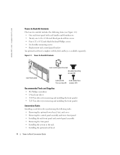
www.dell.com | support.dell.com Tower-to-Rack Kit Contents The tower-to-rack kit includes the following tasks: • Removing the optional tower bezel, feet, and cover • ... x 0.312 6-32 x 0.312 Torx Torx screws (4) screws (21) Recommended Tools and Supplies • #2 Phillips screwdriver • 1/4-inch nut driver • T-10 Torx driver (for removing and installing the front panels) • T-15 Torx driver (for removing and installing the front panels) Conversion Tasks Installing a rack kit involves performing the following items (see Figure...
www.dell.com | support.dell.com Tower-to-Rack Kit Contents The tower-to-rack kit includes the following tasks: • Removing the optional tower bezel, feet, and cover • ... x 0.312 6-32 x 0.312 Torx Torx screws (4) screws (21) Recommended Tools and Supplies • #2 Phillips screwdriver • 1/4-inch nut driver • T-10 Torx driver (for removing and installing the front panels) • T-15 Torx driver (for removing and installing the front panels) Conversion Tasks Installing a rack kit involves performing the following items (see Figure...
Installation and Troubleshooting Guide (.htm)
Page 10
... step for the other three metal feet. See Figure 1-3. c Carefully lift the cover away from the chassis. b Using a #2 Phillips screwdriver or a 1/4-inch nut driver, remove the screw that the metal feet hang over the edge of the system. Figure 1-3. b Slide the system cover back and grasp the cover at ...both ends. www.dell.com | support.dell.com 2 Remove the four metal feet from the system: a Orient the system so that secures each metal foot and pull each foot from the...
... step for the other three metal feet. See Figure 1-3. c Carefully lift the cover away from the chassis. b Using a #2 Phillips screwdriver or a 1/4-inch nut driver, remove the screw that the metal feet hang over the edge of the system. Figure 1-3. b Slide the system cover back and grasp the cover at ...both ends. www.dell.com | support.dell.com 2 Remove the four metal feet from the system: a Orient the system so that secures each metal foot and pull each foot from the...
Installation and Troubleshooting Guide (.htm)
Page 13
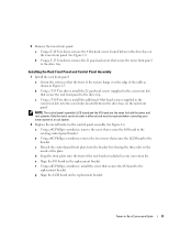
... screw holes located between the drive bays on the inside of the plate. Tower-to the bracket. 5 Remove the tower front panel: a Using a T-10 Torx driver, remove the 4 flat-head screws located between the drive bays on the rack front panel. c Detach the control-panel front plate from the bracket by... remove the two screws that secure the tower front panel to a rack system. 2 Replace the metal bracket in the control panel assembly. c Using a T-10 Torx driver, install the additional 4 flat-head screws (supplied in your tower system to the drive tray. See Figure 1-6. b Using a T-15 Torx...
... screw holes located between the drive bays on the inside of the plate. Tower-to the bracket. 5 Remove the tower front panel: a Using a T-10 Torx driver, remove the 4 flat-head screws located between the drive bays on the rack front panel. c Detach the control-panel front plate from the bracket by... remove the two screws that secure the tower front panel to a rack system. 2 Replace the metal bracket in the control panel assembly. c Using a T-10 Torx driver, install the additional 4 flat-head screws (supplied in your tower system to the drive tray. See Figure 1-6. b Using a T-15 Torx...

Installation and Troubleshooting Guide (.htm)
Page 15
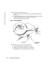
... -Rack Conversion Guide 15 Figure 1-7. See Figure 1-7. Tower-to install in the rack. See Figure 1-7. 3 Using a #2 Phillips screwdriver or 1/4-inch nut driver, remove the three screws from the back of the system. 4 Slide the trim panel backward and then remove the trim panel from the side of... weight of the trim panel. Removing the Trim Panel hex-head Phillips screws (6) shoulder mounting screws (6) 2 Using a #2 Phillips screwdriver or 1/4-inch nut driver, remove the three screws from the chassis. 5 If not already present on its cover as shown in the rack and to each side. Removing the...
... -Rack Conversion Guide 15 Figure 1-7. See Figure 1-7. Tower-to install in the rack. See Figure 1-7. 3 Using a #2 Phillips screwdriver or 1/4-inch nut driver, remove the three screws from the back of the system. 4 Slide the trim panel backward and then remove the trim panel from the side of... weight of the trim panel. Removing the Trim Panel hex-head Phillips screws (6) shoulder mounting screws (6) 2 Using a #2 Phillips screwdriver or 1/4-inch nut driver, remove the three screws from the chassis. 5 If not already present on its cover as shown in the rack and to each side. Removing the...


