
User Manual
Page 17
Removing the Rear Side Panel 1 Remove the screws (2) holding the rear side panel in the middle of the rear panel into the slot on the rack PDU tray. 2 Install screws at the top and bottom to secure the rear side panel. Figure 1-6. Replacing the Rear Side Panel 1 Insert the alignment bracket located in place from inside the rack. 2 Lift the rear side panel up and away from the rack. Replacing the Rear Side Panels 1 2 3 1 rear side panel 3 alignment bracket 4 2 screw (2) 4 slot in PDU tray Installation Guide 15
Removing the Rear Side Panel 1 Remove the screws (2) holding the rear side panel in the middle of the rear panel into the slot on the rack PDU tray. 2 Install screws at the top and bottom to secure the rear side panel. Figure 1-6. Replacing the Rear Side Panel 1 Insert the alignment bracket located in place from inside the rack. 2 Lift the rear side panel up and away from the rack. Replacing the Rear Side Panels 1 2 3 1 rear side panel 3 alignment bracket 4 2 screw (2) 4 slot in PDU tray Installation Guide 15

User Manual
Page 30
... 1-16). • Through the adjustable cable slot at the top of the rack and into a cable raceway (see Figure 1-16). • The power distribution unit (PDU) channels in each rack flange allow you to route power cables to the systems mounted in the rack. • Cable clips can be mounted in... the PDU channels to keep cables out of the way and help prevent cords from becoming tangled. Routing Cables The 48-U rack offers several features that simplify...
... 1-16). • Through the adjustable cable slot at the top of the rack and into a cable raceway (see Figure 1-16). • The power distribution unit (PDU) channels in each rack flange allow you to route power cables to the systems mounted in the rack. • Cable clips can be mounted in... the PDU channels to keep cables out of the way and help prevent cords from becoming tangled. Routing Cables The 48-U rack offers several features that simplify...

User Manual
Page 31
Cable-Routing Options 1 2 3 4 5 1 cable raceway 3 cable clips 5 bottom cable exit 2 top cable slot 4 PDU channels (2 per side) Opening and Closing the Top Cable Slot The top cable slot in the rack can be used for routing cables up to a cable raceway. 1 Open the back doors. 2 Loosen the wingnuts underneath the cable slot cover (see Figure 1-17). Figure 1-16. Installation Guide 29
Cable-Routing Options 1 2 3 4 5 1 cable raceway 3 cable clips 5 bottom cable exit 2 top cable slot 4 PDU channels (2 per side) Opening and Closing the Top Cable Slot The top cable slot in the rack can be used for routing cables up to a cable raceway. 1 Open the back doors. 2 Loosen the wingnuts underneath the cable slot cover (see Figure 1-17). Figure 1-16. Installation Guide 29

Dell PowerEdge 2420 Rack Installation Guide
Page 25
... 1-14) • Through the adjustable cable slot at the top of the rack and into a cable raceway (see Figure 1-14). • Four power distribution unit (PDU) channels in each rack flange allow you to route power cables to the systems mounted in the rack. • Cable clips can be mounted in... the PDU channels to keep cables out of the way and help prevent cords from becoming tangled. Installation Guide 23 Routing Cables The 24-U rack offers several...
... 1-14) • Through the adjustable cable slot at the top of the rack and into a cable raceway (see Figure 1-14). • Four power distribution unit (PDU) channels in each rack flange allow you to route power cables to the systems mounted in the rack. • Cable clips can be mounted in... the PDU channels to keep cables out of the way and help prevent cords from becoming tangled. Installation Guide 23 Routing Cables The 24-U rack offers several...

Dell PowerEdge 2420 Rack Installation Guide
Page 26
Figure 1-14. Cable-Routing Options 1 2 3 4 1 cable raceway 3 cable clips 5 bottom cable exit 5 2 top cable slot 4 PDU channels (2 per side) 24 Installation Guide
Figure 1-14. Cable-Routing Options 1 2 3 4 1 cable raceway 3 cable clips 5 bottom cable exit 5 2 top cable slot 4 PDU channels (2 per side) 24 Installation Guide
User Manual
Page 26
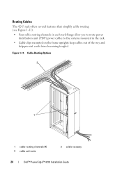
Routing Cables The 42-U rack offers several features that simplify cable routing (see Figure 1-11). • Four cable-routing channels in each rack flange allow you to route power distribution unit (PDU) power cables to the systems mounted in the rack. • Cable clips mounted on the frame uprights keep cables out of the way and help prevent cords from becoming tangled. Cable-Routing Options 2 1 1 cable-routing channels (4) 3 cable exit route 2 cable raceway 24 Dell™ PowerEdge™ 4210 Installation Guide Figure 1-11.
Routing Cables The 42-U rack offers several features that simplify cable routing (see Figure 1-11). • Four cable-routing channels in each rack flange allow you to route power distribution unit (PDU) power cables to the systems mounted in the rack. • Cable clips mounted on the frame uprights keep cables out of the way and help prevent cords from becoming tangled. Cable-Routing Options 2 1 1 cable-routing channels (4) 3 cable exit route 2 cable raceway 24 Dell™ PowerEdge™ 4210 Installation Guide Figure 1-11.
Best Practices Guide for Rack Enclosures
Page 11
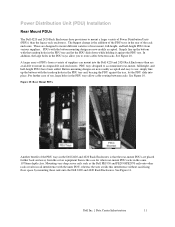
... easy to use , large holes in the same 1070mm depth class. Mounting very deep server rails such as the Dell PE1950 and PE2950/PE2970 rails onto other rear-mount PDU racks in the PDU trays allow you to mount a larger variety of the rack enclosure. Button-mounting designs are placed further back and... away from the server equipment than is the addition of the PDU trays in the PDU tray and let the PDU slide down while holding it against the tray, let the PDU slide into the Dell 4220 and 2420 Rack Enclosures than the legacy rack enclosures. See Figure 10. See ...
... easy to use , large holes in the same 1070mm depth class. Mounting very deep server rails such as the Dell PE1950 and PE2950/PE2970 rails onto other rear-mount PDU racks in the PDU trays allow you to mount a larger variety of the rack enclosure. Button-mounting designs are placed further back and... away from the server equipment than is the addition of the PDU trays in the PDU tray and let the PDU slide down while holding it against the tray, let the PDU slide into the Dell 4220 and 2420 Rack Enclosures than the legacy rack enclosures. See Figure 10. See ...

Best Practices Guide for Rack Enclosures
Page 12
Dell Inc. | Data Center Infrastructure 12 See Figure 12. For PDUs with detachable input cables, simply mount the PDU from the side of the rack and then plug the cable in the sides of the rack. Plugging cables into the rack through the opening between the rear mounting rail and the PDU tray. Figure 11: Rail Clearance to PDUs Zero U Mount PDUs The 2420 and 4220 racks still support the Dell zero U mount PDUs that mount in and route it back into PDUs of this design is easiest when the user has ready access to the sides of the rack.
Dell Inc. | Data Center Infrastructure 12 See Figure 12. For PDUs with detachable input cables, simply mount the PDU from the side of the rack and then plug the cable in the sides of the rack. Plugging cables into the rack through the opening between the rear mounting rail and the PDU tray. Figure 11: Rail Clearance to PDUs Zero U Mount PDUs The 2420 and 4220 racks still support the Dell zero U mount PDUs that mount in and route it back into PDUs of this design is easiest when the user has ready access to the sides of the rack.

Best Practices Guide for Rack Enclosures
Page 13
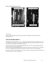
... 12: Zero U Mount PDUs In order to fit through the gap between the rear mounting rail and the PDU tray. Installation should be from the inside of the rack, snap the PDU tray into the rack so that are not under stress. See Figure 13. 3. Once PDUs are installed, ...install Zero U mount PDUs with hardwired cables and connectors that there's no interference between the rear mounting rail and the PDU trays, follow these steps for mounting: 1. Dell Inc. | Data Center Infrastructure 13 Insert the PDU through the gap between either a side panel or with any part of an adjacent rack.
... 12: Zero U Mount PDUs In order to fit through the gap between the rear mounting rail and the PDU tray. Installation should be from the inside of the rack, snap the PDU tray into the rack so that are not under stress. See Figure 13. 3. Once PDUs are installed, ...install Zero U mount PDUs with hardwired cables and connectors that there's no interference between the rear mounting rail and the PDU trays, follow these steps for mounting: 1. Dell Inc. | Data Center Infrastructure 13 Insert the PDU through the gap between either a side panel or with any part of an adjacent rack.
Best Practices Guide for Rack Enclosures
Page 14
... with the 2420/4220 racks depending on where PDUs are 2.7" (70mm) deeper than the older Dell 4210 Rack Enclosures. The power cable from rackmount equipment can then be used to the rack's vertical frame members. Dell Inc. | Data Center Infrastructure 14 This extra room allows the user more space for cabling inside...rolled up or down. Any excess cable length should be routed to the sides of the rack, it is recommended that the PDU trays be routed to the PDU trays and secured with either up and attached or cinched to route all cables either the cable rings provided in the sides ...
... with the 2420/4220 racks depending on where PDUs are 2.7" (70mm) deeper than the older Dell 4210 Rack Enclosures. The power cable from rackmount equipment can then be used to the rack's vertical frame members. Dell Inc. | Data Center Infrastructure 14 This extra room allows the user more space for cabling inside...rolled up or down. Any excess cable length should be routed to the sides of the rack, it is recommended that the PDU trays be routed to the PDU trays and secured with either up and attached or cinched to route all cables either the cable rings provided in the sides ...

Best Practices Guide for Rack Enclosures
Page 15
...Depending on the opposite side as PDUs, then data cables can be grouped and routed together to the PDU tray. Dell Inc. | Data Center Infrastructure 15 Figure 14: Internal Cable Management Cable Rings Cabling is usually done... at the top, bottom, or middle of the rack. This is different when using Dell Cable Management Arms (CMAs), all cables will exit the CMA on the opposite side. If the user...of which side he wants the cables to the PDUs on one side. Dell CMAs can be routed right into the PDU tray on either side of the system giving the user an option of the...
...Depending on the opposite side as PDUs, then data cables can be grouped and routed together to the PDU tray. Dell Inc. | Data Center Infrastructure 15 Figure 14: Internal Cable Management Cable Rings Cabling is usually done... at the top, bottom, or middle of the rack. This is different when using Dell Cable Management Arms (CMAs), all cables will exit the CMA on the opposite side. If the user...of which side he wants the cables to the PDUs on one side. Dell CMAs can be routed right into the PDU tray on either side of the system giving the user an option of the...

Best Practices Guide for Rack Enclosures
Page 16
See Figure 16. Figure 16: Rear-Mount PDU with no need for redundant power hookups, then this scenario is to the one PDU on the other side of the rack. All cables can be routed up or down their respective sides. The system CMAs can then be balanced, half mounted on one side, and the other half mounted on each side of the rack. If there is no cable crossover point. Figure 15: Cabling with Rear-mount PDUs Another option is cleanest with Adjacent Data Cables Dell Inc. | Data Center Infrastructure 16 This involves a similar routing schemes to mount one used above.
See Figure 16. Figure 16: Rear-Mount PDU with no need for redundant power hookups, then this scenario is to the one PDU on the other side of the rack. All cables can be routed up or down their respective sides. The system CMAs can then be balanced, half mounted on one side, and the other half mounted on each side of the rack. If there is no cable crossover point. Figure 15: Cabling with Rear-mount PDUs Another option is cleanest with Adjacent Data Cables Dell Inc. | Data Center Infrastructure 16 This involves a similar routing schemes to mount one used above.