
User Manual
Page 9
... may need the following tools and supplies to install stabilizers accordingly before installing components in a rack could cause the rack to other component is pulled out of the rack with the slide assemblies fully extended. The weight of the rack on racks joined to tip over and cause injury. WARNING: After installing systems in bodily injury...
... may need the following tools and supplies to install stabilizers accordingly before installing components in a rack could cause the rack to other component is pulled out of the rack with the slide assemblies fully extended. The weight of the rack on racks joined to tip over and cause injury. WARNING: After installing systems in bodily injury...

User Manual
Page 10
The hinge pin's retention clip prevents the hinge from pallet) Removing and Replacing the Rack Doors WARNING: Because of the size and weight of the hinge body. 8 Installation Guide • Needle-nose pliers • 4-mm Allen wrench (if you want to reverse the direction that it clears the ...
The hinge pin's retention clip prevents the hinge from pallet) Removing and Replacing the Rack Doors WARNING: Because of the size and weight of the hinge body. 8 Installation Guide • Needle-nose pliers • 4-mm Allen wrench (if you want to reverse the direction that it clears the ...

User Manual
Page 11
Figure 1-1. Installation Guide 9 WARNING: Due to the size and weight of the door's hinge-pin housing, pull the door slightly away from the rack so that the door clears the hinge body. 4 Release the hinge pin. 5 Lift the door upward so that you lay the removed door flat with ...
Figure 1-1. Installation Guide 9 WARNING: Due to the size and weight of the door's hinge-pin housing, pull the door slightly away from the rack so that the door clears the hinge body. 4 Release the hinge pin. 5 Lift the door upward so that you lay the removed door flat with ...

User Manual
Page 12
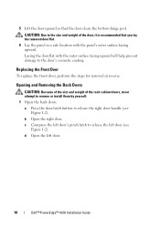
Opening the Back Doors 1 1 door handle 2 2 back door (2) 10 Installation Guide Figure 1-2. Opening and Removing the Back Doors WARNING: Because of the size and weight of the rack cabinet doors, never attempt to remove or install them by yourself. 1 Turn the door handle and open the back doors (see Figure 1-2). Replacing the Front Door To replace the front door, perform the steps for removal in reverse.
Opening the Back Doors 1 1 door handle 2 2 back door (2) 10 Installation Guide Figure 1-2. Opening and Removing the Back Doors WARNING: Because of the size and weight of the rack cabinet doors, never attempt to remove or install them by yourself. 1 Turn the door handle and open the back doors (see Figure 1-2). Replacing the Front Door To replace the front door, perform the steps for removal in reverse.

User Manual
Page 13
... out of the door's hinge-pin housing. Removing the Back Doors 1 2 3 1 hinge pin 3 hinge-pin housing 2 hinge body WARNING: Due to prevent them from the rack. Figure 1-3. You will hear a click sound as you lay the removed door flat with its outer surface facing upward. The hinge pins are designed to...
... out of the door's hinge-pin housing. Removing the Back Doors 1 2 3 1 hinge pin 3 hinge-pin housing 2 hinge body WARNING: Due to prevent them from the rack. Figure 1-3. You will hear a click sound as you lay the removed door flat with its outer surface facing upward. The hinge pins are designed to...

User Manual
Page 25
...the stabilizer feet, which are closed and the badge is supporting the weight of the rack. Proper contact with the vertical bar on the corners of the rack and prevents the rack from tipping over . NOTE: If the rack is in any direction. WARNING: Adjust the leveling feet until each ... the leveling feet are not supporting the weight of the rack do not rise more than 9.5 mm (3/8 inch) above the floor. WARNING: Always level the rack and install the stabilizing feet before moving the rack. Installation Guide 23 Before you level your rack is resting on each leveling foot rests ...
...the stabilizer feet, which are closed and the badge is supporting the weight of the rack. Proper contact with the vertical bar on the corners of the rack and prevents the rack from tipping over . NOTE: If the rack is in any direction. WARNING: Adjust the leveling feet until each ... the leveling feet are not supporting the weight of the rack do not rise more than 9.5 mm (3/8 inch) above the floor. WARNING: Always level the rack and install the stabilizing feet before moving the rack. Installation Guide 23 Before you level your rack is resting on each leveling foot rests ...

User Manual
Page 34
... removed, on which rack you place the gasket strip segments, as long as they protect both racks from both racks. 2 Unpack the coupling kit, shown in contact with the adjacent rack (see Figure 1-20). Coupling Two Racks WARNING: Because of the size and weight of the rack cabinets, never attempt ...to be in Figure 1-19. The contents of the rack coupling kit include: &#...
... removed, on which rack you place the gasket strip segments, as long as they protect both racks from both racks. 2 Unpack the coupling kit, shown in contact with the adjacent rack (see Figure 1-20). Coupling Two Racks WARNING: Because of the size and weight of the rack cabinets, never attempt ...to be in Figure 1-19. The contents of the rack coupling kit include: &#...

Dell PowerEdge 2420 Rack Installation Guide
Page 9
... pulled out of more than one time. The stabilizer feet help prevent the rack from tipping over , potentially resulting in the rack. Therefore, always install the stabilizer feet before installing components in bodily injury under certain circumstances. The weight of the rack with the slide assemblies fully extended. WARNING: For stability, you want to...
... pulled out of more than one time. The stabilizer feet help prevent the rack from tipping over , potentially resulting in the rack. Therefore, always install the stabilizer feet before installing components in bodily injury under certain circumstances. The weight of the rack with the slide assemblies fully extended. WARNING: For stability, you want to...

Dell PowerEdge 2420 Rack Installation Guide
Page 11
... the back doors (see Figure 1-2). Figure 1-2. 3 While holding the hinge pin out of the door's hinge-pin housing, pull the door slightly away from the rack so that the door clears the hinge body. 4 Release the hinge pin. 5 Lift the door upward so that you lay the removed door flat with... the front door, perform the steps for removal in a safe location with the outer surface facing upward will help prevent damage to the size and weight of the door, it is recommended that the door clears the bottom hinge post WARNING: Due to the door's badge and cosmetic coating.
... the back doors (see Figure 1-2). Figure 1-2. 3 While holding the hinge pin out of the door's hinge-pin housing, pull the door slightly away from the rack so that the door clears the hinge body. 4 Release the hinge pin. 5 Lift the door upward so that you lay the removed door flat with... the front door, perform the steps for removal in a safe location with the outer surface facing upward will help prevent damage to the size and weight of the door, it is recommended that the door clears the bottom hinge post WARNING: Due to the door's badge and cosmetic coating.

Dell PowerEdge 2420 Rack Installation Guide
Page 12
The hinge pins are designed to prevent them from the rack. c Pull the door away from being pulled out of the hinge body. d Lay the door in a safe location with the outer surface facing upward will ... Back Doors 1 2 3 1 hinge pin 3 hinge-pin housing 2 hinge body WARNING: Due to the door's cosmetic coating. You will help prevent damage to the size and weight of the door, it is recommended that you pull the pin out of the door's hinge-pin housing (see Figure 1-3). 2 Remove the right door. a While...
The hinge pins are designed to prevent them from the rack. c Pull the door away from being pulled out of the hinge body. d Lay the door in a safe location with the outer surface facing upward will ... Back Doors 1 2 3 1 hinge pin 3 hinge-pin housing 2 hinge body WARNING: Due to the door's cosmetic coating. You will help prevent damage to the size and weight of the door, it is recommended that you pull the pin out of the door's hinge-pin housing (see Figure 1-3). 2 Remove the right door. a While...

Dell PowerEdge 2420 Rack Installation Guide
Page 20
... firmly on the floor. If you exceed 9.5 mm of clearance between the floor and the casters as you level your rack is supporting the weight of the rack and prevents the rack from the top of the rack. If the leveling feet are designed to install the stabilizer feet, which are not supporting the... weight of the door and slide the badge hooks over . Always retract the leveling feet before you might not be able to align the rack in the rack, deploy and adjust the leveling feet. d Lift up on the badge ...
... firmly on the floor. If you exceed 9.5 mm of clearance between the floor and the casters as you level your rack is supporting the weight of the rack and prevents the rack from the top of the rack. If the leveling feet are designed to install the stabilizer feet, which are not supporting the... weight of the door and slide the badge hooks over . Always retract the leveling feet before you might not be able to align the rack in the rack, deploy and adjust the leveling feet. d Lift up on the badge ...

Coupling Two Dell PowerEdge 4220 Racks
Page 1
... by yourself. About Warnings WARNING: A WARNING indicates a potential for property damage, personal injury, or death. Coupling Two Racks WARNING: Because of the size and weight of the rack coupling kit include: • One gasket strip • Four coupling brackets Figure 1-1. See "Removing the Front Door", "Opening and Removing the Back Doors", and "Removing...
... by yourself. About Warnings WARNING: A WARNING indicates a potential for property damage, personal injury, or death. Coupling Two Racks WARNING: Because of the size and weight of the rack coupling kit include: • One gasket strip • Four coupling brackets Figure 1-1. See "Removing the Front Door", "Opening and Removing the Back Doors", and "Removing...

Installing rack stabilizer feet
Page 1
...weight of more than one extended system could cause the rack to tip over and cause injury. NOTE: For complete rack installation instructions, see your rack installation guide. Install stabilizer feet on the rack as follows: • Install front and side stabilizer feet on a standalone rack. • Install front stabilizer feet on all racks... installed in a suite, and install left or right stabilizer feet on the racks at one system out of the rack on its slide assemblies at each end of the rack cabinet. Recommended Tools and Supplies You may need the following tools and supplies...
...weight of more than one extended system could cause the rack to tip over and cause injury. NOTE: For complete rack installation instructions, see your rack installation guide. Install stabilizer feet on the rack as follows: • Install front and side stabilizer feet on a standalone rack. • Install front stabilizer feet on all racks... installed in a suite, and install left or right stabilizer feet on the racks at one system out of the rack on its slide assemblies at each end of the rack cabinet. Recommended Tools and Supplies You may need the following tools and supplies...
User Manual
Page 7
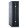
... System rack kits are considered to be included in a rack. Also refer to any other rack, be installed in serious injury. Thus, "component" refers to the rack installation documentation accompanying the system and the rack for rack stability and safety. The weight of ...racks. The installation of your responsibility to other rack cabinet has not been approved by trained service technicians. Dell™ PowerEdge™ 4210 Installation Guide 5 SAFETY: Rack Mounting of the rack on racks joined to ensure that the rack meets the specifications of system and rack...
... System rack kits are considered to be included in a rack. Also refer to any other rack, be installed in serious injury. Thus, "component" refers to the rack installation documentation accompanying the system and the rack for rack stability and safety. The weight of ...racks. The installation of your responsibility to other rack cabinet has not been approved by trained service technicians. Dell™ PowerEdge™ 4210 Installation Guide 5 SAFETY: Rack Mounting of the rack on racks joined to ensure that the rack meets the specifications of system and rack...

User Manual
Page 8
..., you should accomplish this entire procedure carefully. 6 Dell™ PowerEdge™ 4210 Installation Guide Install front and side stabilizers on the rack, make sure that the stabilizers are secured to the rack, extended to the floor, and that the rack is provided to the height and weight of the rack, a minimum of two people should read through the...
..., you should accomplish this entire procedure carefully. 6 Dell™ PowerEdge™ 4210 Installation Guide Install front and side stabilizers on the rack, make sure that the stabilizers are secured to the rack, extended to the floor, and that the rack is provided to the height and weight of the rack, a minimum of two people should read through the...
User Manual
Page 9
... extended. Important Safety Information Observe the safety precautions in the rack. This becomes increasingly important when systems are important to prevent injury to yourself and to tip over . The weight of more than one time. Avoid long or steep inclines ...installed could cause the rack to others who may occur. Dell™ PowerEdge™ 4210 Installation Guide 7 The stabilizer feet help prevent the rack from rolling. Rack Stabilizer Feet CAUTION: Installing systems in a rack, never pull more than one system out of the rack with components installed. ...
... extended. Important Safety Information Observe the safety precautions in the rack. This becomes increasingly important when systems are important to prevent injury to yourself and to tip over . The weight of more than one time. Avoid long or steep inclines ...installed could cause the rack to others who may occur. Dell™ PowerEdge™ 4210 Installation Guide 7 The stabilizer feet help prevent the rack from rolling. Rack Stabilizer Feet CAUTION: Installing systems in a rack, never pull more than one system out of the rack with components installed. ...
User Manual
Page 10
...) 8 Removing high-density rear door panels Recommended Tools and Supplies You may need the following tools and supplies to install the rack: • #2 Phillips screwdriver • Flat head screwdriver • 12-mm wrench • Needle-nose pliers • 4-mm Allen wrench (if...8226; Keys to the rack doors and side panels Removing and Replacing the Rack Doors CAUTION: Because of the size and weight of the rack cabinet doors, never attempt to release the door handle, then open the front door all the way (see Figure 1-1). 8 Dell™ PowerEdge™ 4210 Installation Guide CAUTION: Store...
...) 8 Removing high-density rear door panels Recommended Tools and Supplies You may need the following tools and supplies to install the rack: • #2 Phillips screwdriver • Flat head screwdriver • 12-mm wrench • Needle-nose pliers • 4-mm Allen wrench (if...8226; Keys to the rack doors and side panels Removing and Replacing the Rack Doors CAUTION: Because of the size and weight of the rack cabinet doors, never attempt to release the door handle, then open the front door all the way (see Figure 1-1). 8 Dell™ PowerEdge™ 4210 Installation Guide CAUTION: Store...
User Manual
Page 12
... door flat with the panel's outer surface facing upward. c Compress the left door. 10 Dell™ PowerEdge™ 4210 Installation Guide d Open the left door's pinch latch to the door's cosmetic coating. 5 ...yourself. 1 Open the back doors. Opening and Removing the Back Doors CAUTION: Because of the size and weight of the door, it is recommended that the door clears the bottom hinge post. Replacing the Front Door To... the left door (see Figure 1-2). CAUTION: Due to the size and weight of the rack cabinet doors, never attempt to release the right door handle (see Figure 1-2).
... door flat with the panel's outer surface facing upward. c Compress the left door. 10 Dell™ PowerEdge™ 4210 Installation Guide d Open the left door's pinch latch to the door's cosmetic coating. 5 ...yourself. 1 Open the back doors. Opening and Removing the Back Doors CAUTION: Because of the size and weight of the door, it is recommended that the door clears the bottom hinge post. Replacing the Front Door To... the left door (see Figure 1-2). CAUTION: Due to the size and weight of the rack cabinet doors, never attempt to release the right door handle (see Figure 1-2).

User Manual
Page 15
Replacing the Back Doors To replace the back doors, perform the steps for installing systems in a rack, having the sides open makes it easier to install slide assemblies and support rails and to reverse the direction that the front door opens... for removal in order to remove or install them by yourself. Removing a Side Panel 1 2 3 1 side panel (2) 3 handles (2) 2 locks (2) Dell™ PowerEdge™ 4210 Installation Guide 13 Removing the Side Panels CAUTION: Because of the size and weight of the panel (see Figure 1-4). NOTE: You must remove the side panels in reverse.
Replacing the Back Doors To replace the back doors, perform the steps for installing systems in a rack, having the sides open makes it easier to install slide assemblies and support rails and to reverse the direction that the front door opens... for removal in order to remove or install them by yourself. Removing a Side Panel 1 2 3 1 side panel (2) 3 handles (2) 2 locks (2) Dell™ PowerEdge™ 4210 Installation Guide 13 Removing the Side Panels CAUTION: Because of the size and weight of the panel (see Figure 1-4). NOTE: You must remove the side panels in reverse.

User Manual
Page 16
...-nose pliers, remove the retention clip, and slide the hinge pin out of the hinge body. 14 Dell™ PowerEdge™ 4210 Installation Guide Replacing the Side Panels CAUTION: Because of the size and weight of the rack cabinet side panels, never attempt to remove or install them on the side opposite their original positions...
...-nose pliers, remove the retention clip, and slide the hinge pin out of the hinge body. 14 Dell™ PowerEdge™ 4210 Installation Guide Replacing the Side Panels CAUTION: Because of the size and weight of the rack cabinet side panels, never attempt to remove or install them on the side opposite their original positions...


