
Microprocessor Installation Information
Page 1
...Installation Information CAUTION: Any installation that requires removal of the system cover is strictly forbidden. NOTICE: Failure to update your system to the latest BIOS and BMC firmware versions prior to installing the microprocessor can result in your ... your system BIOS version in this document to refer to change without the written permission of Intel Corporation. NOTICE: If the front of Dell Inc.; About Cautions CAUTION: A CAUTION indicates a potential for complete information about safety precautions, working inside the computer and protecting against electrostatic...
...Installation Information CAUTION: Any installation that requires removal of the system cover is strictly forbidden. NOTICE: Failure to update your system to the latest BIOS and BMC firmware versions prior to installing the microprocessor can result in your ... your system BIOS version in this document to refer to change without the written permission of Intel Corporation. NOTICE: If the front of Dell Inc.; About Cautions CAUTION: A CAUTION indicates a potential for complete information about safety precautions, working inside the computer and protecting against electrostatic...
Trusted Platform Module (TPM) Update
Page 1
... in trademarks and trade names other than its own. November 2007 All rights reserved. disclaims any manner whatsoever without notice. © 2007 Dell Inc. is subject to either the entities claiming the marks and names or their products. Trademarks used in this text...may be used in this document to refer to change without the written permission of Dell Inc. Dell Inc. Disregard any TPM options listed in the "Using the System Setup Program" chapter of your Hardware Owner's Manual. Trusted Platform Module (TPM) Update Systems that are shipping in China are trademarks of...
... in trademarks and trade names other than its own. November 2007 All rights reserved. disclaims any manner whatsoever without notice. © 2007 Dell Inc. is subject to either the entities claiming the marks and names or their products. Trademarks used in this text...may be used in this document to refer to change without the written permission of Dell Inc. Dell Inc. Disregard any TPM options listed in the "Using the System Setup Program" chapter of your Hardware Owner's Manual. Trusted Platform Module (TPM) Update Systems that are shipping in China are trademarks of...
Information Update
Page 1
Dell™ PowerEdge™ 2950 Systems Information Update
Dell™ PowerEdge™ 2950 Systems Information Update
Information Update
Page 3
Safeguarding Encrypted Data 9 System Message Update 10 LCD Status Messages Update 15 Contents 3 Contents Non-Optimal Memory Configurations 5 PowerEdge 2950 III - New System Features 5 New Performance Features 5 New High-Efficiency Power Supply and Power Monitoring Features 5 New I/O and Storage Features 6 New Security Features 6 Optional Internal USB Memory Key 6 Installing the Optional Internal USB Memory Key 7 Support for 8-GB Memory Modules - Power 2950 II and PowerEdge 2950 III Systems 9 System Board Replacement - PowerEdge 2950 III Systems 9 Processor Upgrades -
Safeguarding Encrypted Data 9 System Message Update 10 LCD Status Messages Update 15 Contents 3 Contents Non-Optimal Memory Configurations 5 PowerEdge 2950 III - New System Features 5 New Performance Features 5 New High-Efficiency Power Supply and Power Monitoring Features 5 New I/O and Storage Features 6 New Security Features 6 Optional Internal USB Memory Key 6 Installing the Optional Internal USB Memory Key 7 Support for 8-GB Memory Modules - Power 2950 II and PowerEdge 2950 III Systems 9 System Board Replacement - PowerEdge 2950 III Systems 9 Processor Upgrades -
Information Update
Page 4
System Setup Program Update 19 Memory Screen 19 CPU Information Screen 20 Integrated Devices Screen 20 System Security Screen 21 Serial Communication Screen 23 Operating System Information 23 Enumeration of NICs 23 RHEL - Incorrect Processor Information 23 System Support for Microsoft Windows 2000 . . . 24 System Diagnostics Update 24 4 Contents
System Setup Program Update 19 Memory Screen 19 CPU Information Screen 20 Integrated Devices Screen 20 System Security Screen 21 Serial Communication Screen 23 Operating System Information 23 Enumeration of NICs 23 RHEL - Incorrect Processor Information 23 System Support for Microsoft Windows 2000 . . . 24 System Diagnostics Update 24 4 Contents
Information Update
Page 5
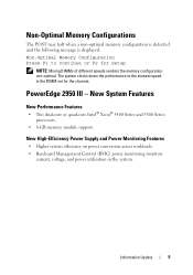
The system clocks down the performance to continue or F2 for the channel. Information Update 5 New High-Efficiency Power Supply and Power Monitoring Features • Higher system efficiency on power conversion across workloads. • Baseboard Management Control (... non-optimal memory configuration is detected and the following message is displayed: Non-Optimal Memory Configuration Press F1 to the slowest speed in the system. PowerEdge 2950 III - New System Features New Performance Features • Two dual-core or quad-core Intel® Xeon® 5400 Series and 5300 Series ...
The system clocks down the performance to continue or F2 for the channel. Information Update 5 New High-Efficiency Power Supply and Power Monitoring Features • Higher system efficiency on power conversion across workloads. • Baseboard Management Control (... non-optimal memory configuration is detected and the following message is displayed: Non-Optimal Memory Configuration Press F1 to the slowest speed in the system. PowerEdge 2950 III - New System Features New Performance Features • Two dual-core or quad-core Intel® Xeon® 5400 Series and 5300 Series ...

Information Update
Page 6
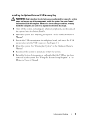
... boot from the USB memory key, you must conform to the following maximum dimensions: 11mm thick (0.43") x 23.2mm width (0.91") x 67mm length (2.64"). 6 Information Update NOTE: USB keys that accompanied the USB memory key. To use with a boot image and then specify the USB memory key in the boot sequence...
... boot from the USB memory key, you must conform to the following maximum dimensions: 11mm thick (0.43") x 23.2mm width (0.91") x 67mm length (2.64"). 6 Information Update NOTE: USB keys that accompanied the USB memory key. To use with a boot image and then specify the USB memory key in the boot sequence...
Information Update
Page 7
Information Update 7 See "Closing the System" in the Hardware Owner's Manual. 3 Locate the USB connector on the sideplane board, and insert the USB memory key into the ...
Information Update 7 See "Closing the System" in the Hardware Owner's Manual. 3 Locate the USB connector on the sideplane board, and insert the USB memory key into the ...
Information Update
Page 8
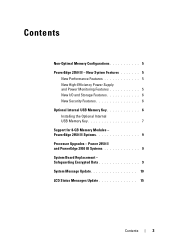
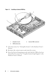
See "Using the System Setup Program" in the Hardware Owner's Manual. 8 Reconnect the system to power and restart the system. 9 Enter the System Setup program and verify that the USB key has been detected by the system. Figure 1-1. Installing an Internal USB Key 3 2 1 1 sideplane board 3 USB memory key 2 internal USB connector 7 Close the system. See "Closing the System" in the Hardware Owner's Manual. 8 Information Update
See "Using the System Setup Program" in the Hardware Owner's Manual. 8 Reconnect the system to power and restart the system. 9 Enter the System Setup program and verify that the USB key has been detected by the system. Figure 1-1. Installing an Internal USB Key 3 2 1 1 sideplane board 3 USB memory key 2 internal USB connector 7 Close the system. See "Closing the System" in the Hardware Owner's Manual. 8 Information Update
Information Update
Page 9
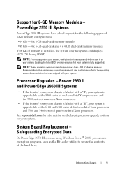
Support for your system. Processor Upgrades - Information Update 9 NOTE: Prior to secure the contents of memory is fully supported. System Board Replacement - Safeguarding Encrypted Data On PowerEdge 2950 III systems using Windows Server® 2008, you can use encryption programs, such as the BitLocker utility, ...rank memory modules If 64 GB of the hard drive. For more than 4 GB of quad-core Intel Xeon processors. See support.dell.com for information on the latest processor upgrade options for 8-GB Memory Modules - Loading the latest BIOS version ensures that the latest ...
Support for your system. Processor Upgrades - Information Update 9 NOTE: Prior to secure the contents of memory is fully supported. System Board Replacement - Safeguarding Encrypted Data On PowerEdge 2950 III systems using Windows Server® 2008, you can use encryption programs, such as the BitLocker utility, ...rank memory modules If 64 GB of the hard drive. For more than 4 GB of quad-core Intel Xeon processors. See support.dell.com for information on the latest processor upgrade options for 8-GB Memory Modules - Loading the latest BIOS version ensures that the latest ...
Information Update
Page 10
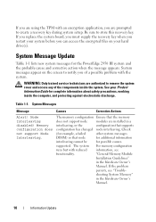
... Manual. System messages appear on your hard drive(s). "General Memory Module Installation Guidelines" in the Hardware Owner's Manual. 10 Information Update Be sure to create a recovery key during system setup. Table 1-1. The memory configuration Ensure that the memory does not support node ... to remove the system cover and access any of a possible problem with reduced information, see "Trouble- Check (for the PowerEdge 2950 III system and the probable cause and corrective action when the message appears. The system For memory configuration runs but with the...
... Manual. System messages appear on your hard drive(s). "General Memory Module Installation Guidelines" in the Hardware Owner's Manual. 10 Information Update Be sure to create a recovery key during system setup. Table 1-1. The memory configuration Ensure that the memory does not support node ... to remove the system cover and access any of a possible problem with reduced information, see "Trouble- Check (for the PowerEdge 2950 III system and the probable cause and corrective action when the message appears. The system For memory configuration runs but with the...
Information Update
Page 11
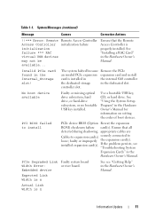
... failure Ensure that all detected during shadowing. The system halted because Remove the PCIe an invalid PCIe expansion expansion card and install card is n Information Update 11 controller slot. appropriate cables are Cables to expansion card(s) securely connected to install PCIe device BIOS (Option Reseat the expansion ROM) checksum failure card...
... failure Ensure that all detected during shadowing. The system halted because Remove the PCIe an invalid PCIe expansion expansion card and install card is n Information Update 11 controller slot. appropriate cables are Cables to expansion card(s) securely connected to install PCIe device BIOS (Option Reseat the expansion ROM) checksum failure card...

Information Update
Page 12
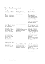
See "Getting Help" in the Hardware Owner's Manual. If the problem persists, see "Getting Help" in the Hardware Owner's Manual. 12 Information Update See "Expansion Cards" in the Hardware Owner's Manual. If the problem persists, see "Getting Help" in the Hardware Owner's Manual. Table 1-1. System Messages (continued) Message ...
See "Getting Help" in the Hardware Owner's Manual. If the problem persists, see "Getting Help" in the Hardware Owner's Manual. 12 Information Update See "Expansion Cards" in the Hardware Owner's Manual. If the problem persists, see "Getting Help" in the Hardware Owner's Manual. Table 1-1. System Messages (continued) Message ...
Information Update
Page 13
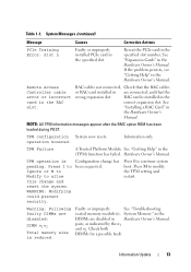
... wrong expansion slot. pairs, as indicated by the n1 and n2. If the problem persists, see "Getting Help" in the (TPM) function has failed. Information Update 13 Reseat the PCIe card in the specified slot. TPM configuration System now resets. Information only. Hardware Owner's Manual. WARNING: Modifying could prevent security. Press...
... wrong expansion slot. pairs, as indicated by the n1 and n2. If the problem persists, see "Getting Help" in the (TPM) function has failed. Information Update 13 Reseat the PCIe card in the specified slot. TPM configuration System now resets. Information only. Hardware Owner's Manual. WARNING: Modifying could prevent security. Press...
Information Update
Page 14
...See the applicable troubleshooting section in See "Troubleshooting Your System" in the Hardware Owner's Manual. No micro Micro code update failed. Table 1-1. See "General Memory Module Installation Guidelines" in the Hardware Owner's Manual. Reseat the USB device or... system runs but with reduced functionality. Please check the system event log! code update loaded See "Getting Help" in the for any faulty components specified in the Hardware Owner's Manual. 14 Information Update If the problem persists, see "Troubleshooting a Hard Drive" in the SEL. For...
...See the applicable troubleshooting section in See "Troubleshooting Your System" in the Hardware Owner's Manual. No micro Micro code update failed. Table 1-1. See "General Memory Module Installation Guidelines" in the Hardware Owner's Manual. Reseat the USB device or... system runs but with reduced functionality. Please check the system event log! code update loaded See "Getting Help" in the for any faulty components specified in the Hardware Owner's Manual. 14 Information Update If the problem persists, see "Troubleshooting a Hard Drive" in the SEL. For...
Information Update
Page 15
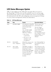
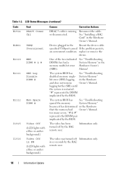
... E1118 Text SYSTEM NAME FAILSAFE, Call Support CPU Temp Interface Causes Corrective Actions A 62-character string that can occur on the PowerEdge 2950 III system and the probable cause for each message. See "Getting Help" in the System Setup program. If the problem persists,...documentation. Table 1-2. Consequently, the BMC increases the CPU fan speed to determine the CPU(s) temperature status. LCD Status Messages Update Table 1-2 lists updates to the LCD status messages that can be defined by the user in the Hardware Owner's Manual. The LCD messages refer...
... E1118 Text SYSTEM NAME FAILSAFE, Call Support CPU Temp Interface Causes Corrective Actions A 62-character string that can occur on the PowerEdge 2950 III system and the probable cause for each message. See "Getting Help" in the System Setup program. If the problem persists,...documentation. Table 1-2. Consequently, the BMC increases the CPU fan speed to determine the CPU(s) temperature status. LCD Status Messages Update Table 1-2 lists updates to the LCD status messages that can be defined by the user in the Hardware Owner's Manual. The LCD messages refer...
Information Update
Page 16
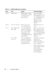
... parity error on a component that resides in PCI configuration space at bus ##, device ##, function ##. See "Expansion Card Risers" in the Hardware Owner's Manual. 16 Information Update Table 1-2. Check the AC power source. LCD Status Messages (continued) Code E1211 Text ROMB Batt Causes RAID battery is faulty. The system BIOS has reported...
... parity error on a component that resides in PCI configuration space at bus ##, device ##, function ##. See "Expansion Card Risers" in the Hardware Owner's Manual. 16 Information Update Table 1-2. Check the AC power source. LCD Status Messages (continued) Code E1211 Text ROMB Batt Causes RAID battery is faulty. The system BIOS has reported...
Information Update
Page 17
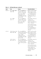
... E171F Text Causes Corrective Actions PCI SERR B## D## F## The system BIOS has reported a PCI system error on a component that resides in the Hardware slot. Manual. Information Update 17 Remove and reseat the PCIe expansion cards. Reinstall the expansioncard riser. See "Expansion Card Risers" in the Hardware Owner's Manual. See on a component that...
... E171F Text Causes Corrective Actions PCI SERR B## D## F## The system BIOS has reported a PCI system error on a component that resides in the Hardware slot. Manual. Information Update 17 Remove and reseat the PCIe expansion cards. Reinstall the expansioncard riser. See "Expansion Card Risers" in the Hardware Owner's Manual. See on a component that...
Information Update
Page 18
... has See "Troubleshooting disabled memory single- The video was turned off by the BIOS. "#" represents the DIMM implicated by the RAC remote user. 18 Information Update One of the two indicated See "Troubleshooting DIMMs has had Owner's Manual. System Memory" bit error (SBE) logging, in the memory multi-bit error Hardware...
... has See "Troubleshooting disabled memory single- The video was turned off by the BIOS. "#" represents the DIMM implicated by the RAC remote user. 18 Information Update One of the two indicated See "Troubleshooting DIMMs has had Owner's Manual. System Memory" bit error (SBE) logging, in the memory multi-bit error Hardware...

Information Update
Page 19
... system memory speed. When set to Spare Mode, the first rank of memory on the Memory Information screen. System Setup Program Update Memory Screen Table 1-3 lists the descriptions for the information fields that appear on each DIMM is reserved for memory sparing. Displays ...Node Interleaving field must be set to Enabled, the memory runs at a reduced speed to Disabled, the memory runs at system boot. Information Update 19 Enables or disables the redundant memory feature. Displays the type of video memory. Specifies whether system memory tests are Enabled and Disabled. ...
... system memory speed. When set to Spare Mode, the first rank of memory on the Memory Information screen. System Setup Program Update Memory Screen Table 1-3 lists the descriptions for the information fields that appear on each DIMM is reserved for memory sparing. Displays ...Node Interleaving field must be set to Enabled, the memory runs at a reduced speed to Disabled, the memory runs at system boot. Information Update 19 Enables or disables the redundant memory feature. Displays the type of video memory. Specifies whether system memory tests are Enabled and Disabled. ...


